Dell PowerConnect J-SRX100 Hardware Guide - Page 37
J-SRX100 Services Gateway Rack Requirements
 |
View all Dell PowerConnect J-SRX100 manuals
Add to My Manuals
Save this manual to your list of manuals |
Page 37 highlights
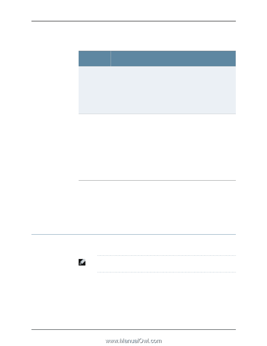
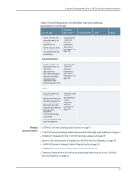
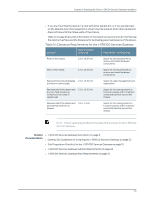
Chapter 3: Preparing the Site for J-SRX100 Services Gateway Installation Table 12: J-SRX100 Services Gateway Cabinet Requirements (continued) Cabinet Requirements Specifications Clearance requirements • The cabinet is at least 1 U (1.75 in. or 4.5 cm) high. • The outer edges of the mounting brackets extend the width of either chassis to 19 in. (48.3 cm), and the front of the chassis extends approximately 0.5 in. (1.27 cm) beyond the mounting brackets. • The minimum total clearance inside the cabinet is 30.7 in. (78 cm) between the inside of the front door and the inside of the rear door. NOTE: The holes for the mounting brackets chassis are spaced 1.25 in. (3.2 cm) apart, measured from the center of the hole. Cabinet airflow requirements • Ensure sufficient ventilation through the cabinet is sufficient to prevent overheating. • Ensure adequate cool air supply to dissipate the thermal output of the device. • Install the device as close as possible to the front of the cabinet so that the cable management system clears the inside of the front door. Installing the chassis close to the front of the cabinet maximizes the clearance in the rear of the cabinet for critical airflow. • Route and dress all cables to minimize the blockage of airflow to and from the chassis. NOTE: A cabinet larger than the minimum required provides better airflow and reduces the chance of overheating. Related • General Site Guidelines for Installing the J-SRX100 Services Gateway on page 22 Documentation • J-SRX100 Services Gateway Rack Requirements on page 23 • Site Preparation Checklist for the J-SRX100 Services Gateway on page 19 • Clearance Requirements for Airflow and Hardware Maintenance of the J-SRX100 Services Gateway on page 24 J-SRX100 Services Gateway Rack Requirements The services gateway can be installed in a rack. Many types of racks are acceptable, including front-mount racks and four-post (telco) racks. NOTE: The services gateway cannot be center-mounted in racks. Table 13 on page 24 provides the details on rack size, clearance, and airflow requirements. 23
-
 1
1 -
2
-
3
-
4
-
5
-
6
-
7
-
8
-
9
-
10
-
11
-
12
-
13
-
14
-
15
-
16
-
17
-
18
-
19
-
20
-
21
-
22
-
23
-
24
-
25
-
26
-
27
-
28
-
29
-
30
-
31
-
 32
32 -
 33
33 -
 34
34 -
 35
35 -
 36
36 -
 37
37 -
 38
38 -
 39
39 -
 40
40 -
 41
41 -
 42
42 -
43
-
44
-
45
-
46
-
47
-
48
-
49
-
50
-
51
-
52
-
53
-
54
-
55
-
56
-
57
-
58
-
59
-
60
-
61
-
62
-
63
-
64
-
65
-
66
-
67
-
68
-
69
-
70
-
71
-
72
-
73
-
74
-
75
-
76
-
77
-
78
-
79
-
80
-
81
-
82
-
83
-
84
-
85
-
86
-
87
-
88
-
89
-
90
-
91
-
92
-
93
-
94
-
95
-
96
-
97
-
98
-
99
-
100
-
101
-
102
-
103
-
104
-
105
-
106
-
107
-
108
-
109
-
110
-
111
-
112
-
113
-
114
-
115
-
116
-
117
-
118
-
119
-
120
-
121
-
122
-
123
-
124
-
125
-
126
-
127
-
128
-
129
-
130
-
131
-
132
-
133
-
134
-
135
-
136
-
137
-
138
-
139
-
140
-
141
-
142
-
143
-
144
-
145
-
146
-
147
-
148
-
149
-
150
-
151
-
152
-
153
-
154
-
155
-
156
-
157
-
158
 |
 |