Dell PowerConnect J-SRX100 Hardware Guide - Page 39
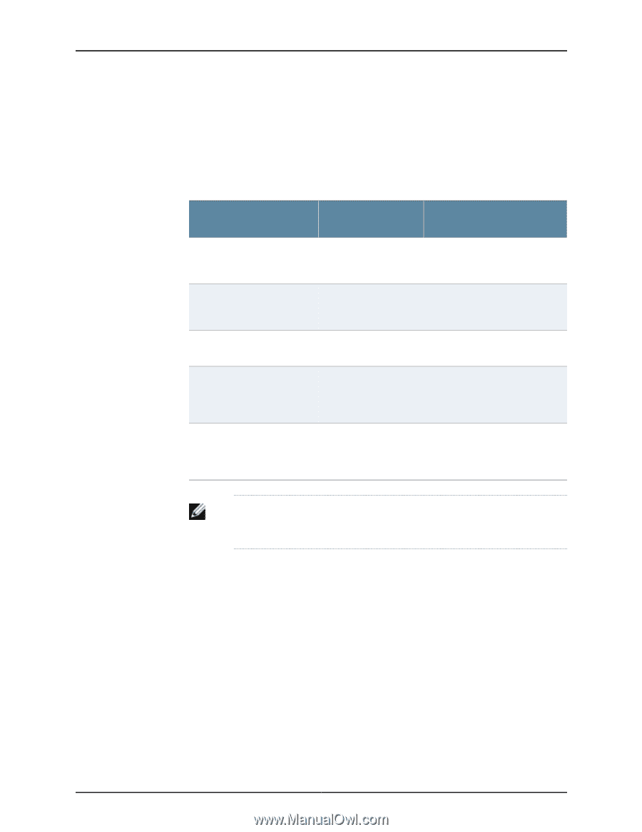
Table 14: Clearance Requirements for the J-SRX100 Services Gateway
 |
View all Dell PowerConnect J-SRX100 manuals
Add to My Manuals
Save this manual to your list of manuals |
Page 39 highlights
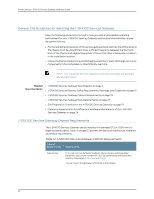
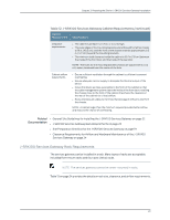
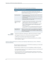
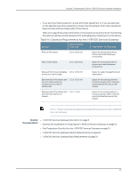
Chapter 3: Preparing the Site for J-SRX100 Services Gateway Installation • If you are mounting the device in a rack with other equipment, or if you are placing it on the desktop near other equipment, ensure that the exhaust from other equipment does not blow into the intake vents of the chassis. Table 14 on page 25 provides information on the clearance requirements for maintaining the optimum airflow and the distances for facilitating easy maintenance of the device. Table 14: Clearance Requirements for the J-SRX100 Services Gateway Location Recommended Clearance Requirement for Clearance Front of the chassis 2.5 in. (6.35 cm) Space for service personnel to remove and install hardware components Rear of the chassis 2.5 in. (6.35 cm) Space for service personnel to remove and install hardware components Between front-mounting flange 2.5 in. (6.35 cm) and rack or cabinet edge Space for cable management and organization Between side of the chassis and any non-heat-producing surface such as a wall or cabinet side 2.5 in. (6.35 cm) Space for the cooling system to function properly and to maintain unrestricted airflow around the chassis Between side of the chassis and devices that have fans or blowers 0.4 in. (1 cm) Space for the cooling system to function properly and to maintain unrestricted airflow around the chassis NOTE: The air vents are provided on the sides of the chassis for the J-SRX100 Services Gateway. Related • J-SRX100 Services Gateway Description on page 3 Documentation • General Site Guidelines for Installing the J-SRX100 Services Gateway on page 22 • Site Preparation Checklist for the J-SRX100 Services Gateway on page 19 • J-SRX100 Services Gateway Cabinet Requirements on page 22 • J-SRX100 Services Gateway Rack Requirements on page 23 25
-
 1
1 -
2
-
3
-
4
-
5
-
6
-
7
-
8
-
9
-
10
-
11
-
12
-
13
-
14
-
15
-
16
-
17
-
18
-
19
-
20
-
21
-
22
-
23
-
24
-
25
-
26
-
27
-
28
-
29
-
30
-
31
-
32
-
33
-
 34
34 -
 35
35 -
 36
36 -
 37
37 -
 38
38 -
 39
39 -
 40
40 -
 41
41 -
 42
42 -
 43
43 -
 44
44 -
45
-
46
-
47
-
48
-
49
-
50
-
51
-
52
-
53
-
54
-
55
-
56
-
57
-
58
-
59
-
60
-
61
-
62
-
63
-
64
-
65
-
66
-
67
-
68
-
69
-
70
-
71
-
72
-
73
-
74
-
75
-
76
-
77
-
78
-
79
-
80
-
81
-
82
-
83
-
84
-
85
-
86
-
87
-
88
-
89
-
90
-
91
-
92
-
93
-
94
-
95
-
96
-
97
-
98
-
99
-
100
-
101
-
102
-
103
-
104
-
105
-
106
-
107
-
108
-
109
-
110
-
111
-
112
-
113
-
114
-
115
-
116
-
117
-
118
-
119
-
120
-
121
-
122
-
123
-
124
-
125
-
126
-
127
-
128
-
129
-
130
-
131
-
132
-
133
-
134
-
135
-
136
-
137
-
138
-
139
-
140
-
141
-
142
-
143
-
144
-
145
-
146
-
147
-
148
-
149
-
150
-
151
-
152
-
153
-
154
-
155
-
156
-
157
-
158
 |
 |