Dell PowerConnect J-SRX100 Hardware Guide - Page 82
Connecting the Modem to the Console Port on the J-SRX100 Services Gateway
 |
View all Dell PowerConnect J-SRX100 manuals
Add to My Manuals
Save this manual to your list of manuals |
Page 82 highlights
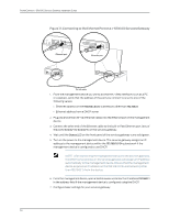
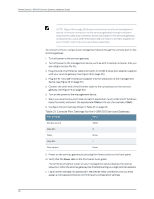
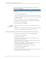
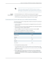
PowerConnect J-SRX100 Services Gateway Hardware Guide Table 22: Port Settings for Configuring the Modem on the Services Gateway End (continued) Port Settings Value Flow control None 5. In the HyperTerminal window, enter AT. For more information on the AT commands, see the Junos OS Administration Guide. An OK response verifies that the modem can communicate successfully with the COM port on the PC or laptop. 6. Configure the modem to answer a call on the first ring by entering ATS0=1. 7. Configure the modem to accept modem control DTR signals by entering AT&D1. 8. Disable flow control by entering AT&K0. 9. Save modem settings by entering AT&W. Related • Connecting the Modem to the Console Port on the J-SRX100 Services Gateway on Documentation page 68 • Connecting to the CLI at the User End for the J-SRX100 Services Gateway on page 69 • J-SRX100 Services Gateway Software Configuration Overview on page 71 Connecting the Modem to the Console Port on the J-SRX100 Services Gateway To connect the dial-up modem to the console port on the services gateway: 1. Turn off power to the services gateway. 2. Turn off power to the modem. 3. Plug one end of the Ethernet cable supplied with your services gateway into the console port on the services gateway. 4. Plug the other end of the CAT-5e (Ethernet cable) into the RJ-45 to DB-9 serial port adapter supplied with your services gateway. 5. Connect the serial port adapter to a separately purchased DB-9 female to DB-25 male adapter or other adapter appropriate for your modem. 6. Plug the modem adapter into the DB-25 connector on the modem. 7. Connect the modem to your telephone network. 8. Turn on the power to the modem. 9. Power on the services gateway by pressing the Power button on the front panel. Verify that the Power LED on the front panel turns green. 68
-
 1
1 -
2
-
3
-
4
-
5
-
6
-
7
-
8
-
9
-
10
-
11
-
12
-
13
-
14
-
15
-
16
-
17
-
18
-
19
-
20
-
21
-
22
-
23
-
24
-
25
-
26
-
27
-
28
-
29
-
30
-
31
-
32
-
33
-
34
-
35
-
36
-
37
-
38
-
39
-
40
-
41
-
42
-
43
-
44
-
45
-
46
-
47
-
48
-
49
-
50
-
51
-
52
-
53
-
54
-
55
-
56
-
57
-
58
-
59
-
60
-
61
-
62
-
63
-
64
-
65
-
66
-
67
-
68
-
69
-
70
-
71
-
72
-
73
-
74
-
75
-
76
-
 77
77 -
 78
78 -
 79
79 -
 80
80 -
 81
81 -
 82
82 -
 83
83 -
 84
84 -
 85
85 -
 86
86 -
 87
87 -
88
-
89
-
90
-
91
-
92
-
93
-
94
-
95
-
96
-
97
-
98
-
99
-
100
-
101
-
102
-
103
-
104
-
105
-
106
-
107
-
108
-
109
-
110
-
111
-
112
-
113
-
114
-
115
-
116
-
117
-
118
-
119
-
120
-
121
-
122
-
123
-
124
-
125
-
126
-
127
-
128
-
129
-
130
-
131
-
132
-
133
-
134
-
135
-
136
-
137
-
138
-
139
-
140
-
141
-
142
-
143
-
144
-
145
-
146
-
147
-
148
-
149
-
150
-
151
-
152
-
153
-
154
-
155
-
156
-
157
-
158
 |
 |
