HP d640 HP D640 High-Volume Printer - User Manual (Printer and Accessories), C - Page 68
Lift paper guides out of their current locations and place them in the new paper size locations.
 |
View all HP d640 manuals
Add to My Manuals
Save this manual to your list of manuals |
Page 68 highlights
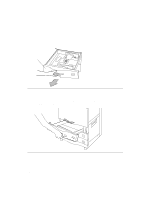
Printer Tasks Adjusting Standard Tray Paper Guides 1. Each paper guide has a blue locking thumbwheel, as shown in Figure 3-5. Guides (3) Locking devices LTR Figure 3-5 Paper guides 2. Turn the blue locking thumbwheels on each paper guide counterclockwise to the OPEN position (Figure 3-6). LTR LGR LTR Figure 3-6 Locking device Lift paper guides out of their current locations and place them in the new paper size locations. The paper size indicators on the tray are visible through the round circle cutout on the paper guide, as shown in Figure 3-7. Printer Tasks 3-5 CLO SE O PEN
-
 1
1 -
2
-
3
-
4
-
5
-
6
-
7
-
8
-
9
-
10
-
11
-
12
-
13
-
14
-
15
-
16
-
17
-
18
-
19
-
20
-
21
-
22
-
23
-
24
-
25
-
26
-
27
-
28
-
29
-
30
-
31
-
32
-
33
-
34
-
35
-
36
-
37
-
38
-
39
-
40
-
41
-
42
-
43
-
44
-
45
-
46
-
47
-
48
-
49
-
50
-
51
-
52
-
53
-
54
-
55
-
56
-
57
-
58
-
59
-
60
-
61
-
62
-
 63
63 -
 64
64 -
 65
65 -
 66
66 -
 67
67 -
 68
68 -
 69
69 -
 70
70 -
 71
71 -
 72
72 -
 73
73 -
74
-
75
-
76
-
77
-
78
-
79
-
80
-
81
-
82
-
83
-
84
-
85
-
86
-
87
-
88
-
89
-
90
-
91
-
92
-
93
-
94
-
95
-
96
-
97
-
98
-
99
-
100
-
101
-
102
-
103
-
104
-
105
-
106
-
107
-
108
-
109
-
110
-
111
-
112
-
113
-
114
-
115
-
116
-
117
-
118
-
119
-
120
-
121
-
122
-
123
-
124
-
125
-
126
-
127
-
128
-
129
-
130
-
131
-
132
-
133
-
134
-
135
-
136
-
137
-
138
-
139
-
140
-
141
-
142
-
143
-
144
-
145
-
146
-
147
-
148
-
149
-
150
-
151
-
152
-
153
-
154
-
155
-
156
-
157
-
158
-
159
-
160
-
161
-
162
-
163
-
164
-
165
-
166
-
167
-
168
-
169
-
170
-
171
-
172
-
173
-
174
-
175
-
176
-
177
-
178
-
179
-
180
-
181
-
182
-
183
-
184
-
185
-
186
-
187
-
188
-
189
-
190
-
191
-
192
-
193
-
194
-
195
-
196
-
197
-
198
-
199
-
200
-
201
-
202
-
203
-
204
-
205
-
206
-
207
-
208
-
209
-
210
-
211
-
212
-
213
-
214
-
215
-
216
-
217
-
218
-
219
-
220
-
221
-
222
-
223
-
224
-
225
-
226
-
227
-
228
-
229
-
230
-
231
-
232
-
233
-
234
-
235
-
236
-
237
-
238
-
239
-
240
-
241
-
242
-
243
-
244
-
245
-
246
-
247
-
248
-
249
-
250
-
251
-
252
-
253
-
254
-
255
-
256
-
257
-
258
-
259
-
260
-
261
-
262
-
263
-
264
-
265
-
266
-
267
-
268
-
269
-
270
-
271
-
272
-
273
-
274
-
275
-
276
-
277
-
278
-
279
-
280
-
281
-
282
-
283
-
284
-
285
-
286
-
287
-
288
-
289
-
290
-
291
-
292
-
293
 |
 |

Adjusting Standard Tray Paper Guides
Printer Tasks
3-5
Printer Tasks
1.
Each paper guide has a blue locking thumbwheel, as shown in Figure
3-5.
Figure 3-5
Paper guides
2.
Turn the blue locking thumbwheels on each paper guide counterclockwise to the OPEN
position (Figure
3-6).
Figure 3-6
Locking device
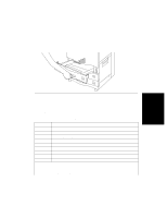
Lift paper guides out of their current locations and place them in the new paper size locations.
The paper size indicators on the tray are visible through the round circle cutout on the paper
guide, as shown in Figure
3-7.
Guides
(3) Locking devices
LTR
LTR
LGR
C
L
O
S
E
O
P
E
N
LTR