IBM 88410EU User Manual - Page 103
Light, diagnostics
 |
View all IBM 88410EU manuals
Add to My Manuals
Save this manual to your list of manuals |
Page 103 highlights
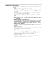
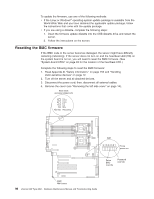
Note: To save the test log to a diskette, you must use a diskette that you have formatted yourself; this function does not work with preformatted diskettes. If the diskette has sufficient space for the test log, the diskette may contain other data. Viewing the system-error log You can also view the system-error log from the diagnostic programs. See the instructions in "Viewing error logs from the diagnostic programs" on page 90. Note: The system-error log on the xSeries 236 is available only with the Remote Supervisor Adapter II SlimLine. For descriptions of the error messages that might appear when you run the diagnostic programs, see "Diagnostic error codes" on page 116. Light path diagnostics The server's light path diagnostics feature provides a path that can be followed in distinct phases to help identify the source of an error. The lights are designed to be followed in an orderly progression, depending on the error. The LEDs are viewed in the following order: 1. Begin on the front panel. 2. Proceed to the light path diagnostics panel. 3. Check the system service label. 4. Look inside the server, if necessary. Many errors are first indicated by the illumination of the system-error light in the operator information panel on the front of the server (see "Server controls, LEDs, and power" on page 3). If the system-error light is lit, one or more lights inside the server might also be lit that can direct you to the source of the error. The system information LED lights to alert you that there might be important information recorded in the system-error log. Complete the following steps to view the LEDs. Note: Read Appendix B, "Safety information," on page 153 and "Installation guidelines" on page 11. 1. Check the system-error LED on the operator information panel on the front of the server. A lit system-error LED indicates that a problem exists. Note: Read "Working inside the server with the power on" on page 12 before removing the left-side cover while the server is connected to a power source. 2. Check the light path diagnostics panel by removing the left-side cover. These LEDs indicate the type of error that has occurred and are described in more detail at "Light path diagnostic errors" on page 114. Chapter 5. Diagnostics 93
-
 1
1 -
2
-
3
-
4
-
5
-
6
-
7
-
8
-
9
-
10
-
11
-
12
-
13
-
14
-
15
-
16
-
17
-
18
-
19
-
20
-
21
-
22
-
23
-
24
-
25
-
26
-
27
-
28
-
29
-
30
-
31
-
32
-
33
-
34
-
35
-
36
-
37
-
38
-
39
-
40
-
41
-
42
-
43
-
44
-
45
-
46
-
47
-
48
-
49
-
50
-
51
-
52
-
53
-
54
-
55
-
56
-
57
-
58
-
59
-
60
-
61
-
62
-
63
-
64
-
65
-
66
-
67
-
68
-
69
-
70
-
71
-
72
-
73
-
74
-
75
-
76
-
77
-
78
-
79
-
80
-
81
-
82
-
83
-
84
-
85
-
86
-
87
-
88
-
89
-
90
-
91
-
92
-
93
-
94
-
95
-
96
-
97
-
 98
98 -
 99
99 -
 100
100 -
 101
101 -
 102
102 -
 103
103 -
 104
104 -
 105
105 -
 106
106 -
 107
107 -
 108
108 -
109
-
110
-
111
-
112
-
113
-
114
-
115
-
116
-
117
-
118
-
119
-
120
-
121
-
122
-
123
-
124
-
125
-
126
-
127
-
128
-
129
-
130
-
131
-
132
-
133
-
134
-
135
-
136
-
137
-
138
-
139
-
140
-
141
-
142
-
143
-
144
-
145
-
146
-
147
-
148
-
149
-
150
-
151
-
152
-
153
-
154
-
155
-
156
-
157
-
158
-
159
-
160
-
161
-
162
-
163
-
164
-
165
-
166
-
167
-
168
-
169
-
170
-
171
-
172
-
173
-
174
-
175
-
176
-
177
-
178
-
179
-
180
-
181
-
182
-
183
-
184
-
185
-
186
-
187
-
188
-
189
-
190
-
191
-
192
-
193
-
194
-
195
-
196
-
197
-
198
-
199
-
200
-
201
-
202
-
203
-
204
-
205
-
206
-
207
-
208
-
209
-
210
 |
 |
