IBM 88410EU User Manual - Page 94
Light, diagnostics, panel
 |
View all IBM 88410EU manuals
Add to My Manuals
Save this manual to your list of manuals |
Page 94 highlights
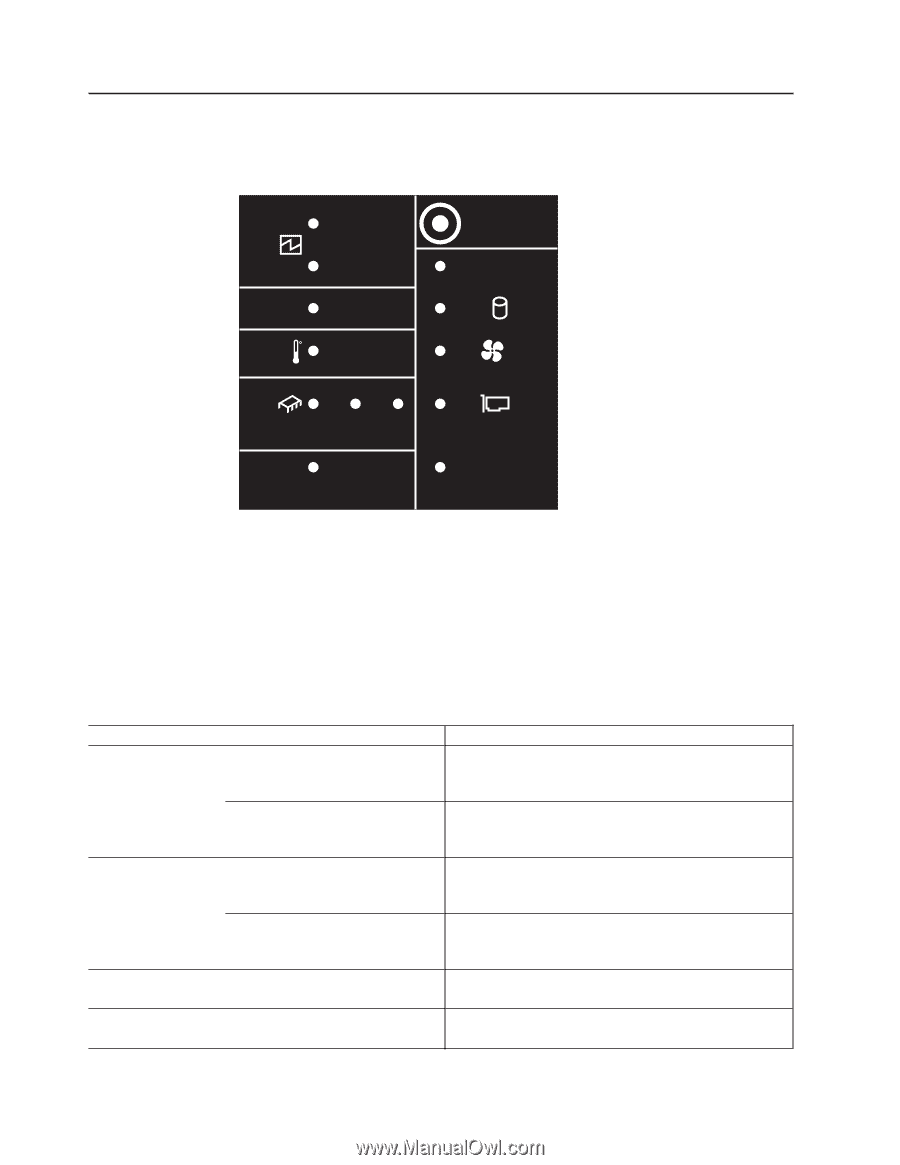
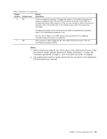
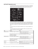
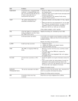
Light path diagnostics panel The following illustration shows the remind button and the LEDs on the light path diagnostics panel. The light path diagnostics panel is inside the server under the left-side cover and the error LEDs are also visible through the left-side cover. 1 POWER SUPPLY 2 CONFIG TEMP REMIND MEMORY DASD/ RAID FAN CPU S_ERR VRM PCI BUS SERVICE NMI PROCESSOR BUS Use the remind button on the light path diagnostic panel to acknowledge that an error has occurred without taking further action. When you push the remind button, the system error LED will flash every 2 seconds until the error is fixed. If another error occurs, the system error LED will then stop flashing and return to a solid on state. For more information about light path diagnostics, see "Light path diagnostics" on page 93. The following table lists the light path diagnostics LEDs, the problems that they indicate, and actions to solve the problems. LED POWER SUPPLY 1 POWER SUPPLY 2 MEMORY CONFIG Problem Action Lit LED: Power supply 1 has failed. 1. Remove ac power from the server. 2. Replace the power supply; then, reconnect the server to ac power and restart the server. Flashing LED: Power supply 1 was Install a new power supply in the PS1 location. removed in a redundant power-supply configuration. Lit LED: Power supply 2 has failed. 1. Remove ac power from the server. 2. Replace the power supply; then, reconnect the server to ac power and restart the server. Flashing LED: Power supply 2 was Install a new power supply in the PS2 location. removed in a redundant power supply configuration. A memory error has occurred. Replace the failing DIMM, indicated by the lit LED on the system board. A configuration error has occurred. Locate the second flashing LED and fix the configuration problem associated with the blinking LED. 84 xSeries 236 Type 8841: Hardware Maintenance Manual and Troubleshooting Guide
-
 1
1 -
2
-
3
-
4
-
5
-
6
-
7
-
8
-
9
-
10
-
11
-
12
-
13
-
14
-
15
-
16
-
17
-
18
-
19
-
20
-
21
-
22
-
23
-
24
-
25
-
26
-
27
-
28
-
29
-
30
-
31
-
32
-
33
-
34
-
35
-
36
-
37
-
38
-
39
-
40
-
41
-
42
-
43
-
44
-
45
-
46
-
47
-
48
-
49
-
50
-
51
-
52
-
53
-
54
-
55
-
56
-
57
-
58
-
59
-
60
-
61
-
62
-
63
-
64
-
65
-
66
-
67
-
68
-
69
-
70
-
71
-
72
-
73
-
74
-
75
-
76
-
77
-
78
-
79
-
80
-
81
-
82
-
83
-
84
-
85
-
86
-
87
-
88
-
 89
89 -
 90
90 -
 91
91 -
 92
92 -
 93
93 -
 94
94 -
 95
95 -
 96
96 -
 97
97 -
 98
98 -
 99
99 -
100
-
101
-
102
-
103
-
104
-
105
-
106
-
107
-
108
-
109
-
110
-
111
-
112
-
113
-
114
-
115
-
116
-
117
-
118
-
119
-
120
-
121
-
122
-
123
-
124
-
125
-
126
-
127
-
128
-
129
-
130
-
131
-
132
-
133
-
134
-
135
-
136
-
137
-
138
-
139
-
140
-
141
-
142
-
143
-
144
-
145
-
146
-
147
-
148
-
149
-
150
-
151
-
152
-
153
-
154
-
155
-
156
-
157
-
158
-
159
-
160
-
161
-
162
-
163
-
164
-
165
-
166
-
167
-
168
-
169
-
170
-
171
-
172
-
173
-
174
-
175
-
176
-
177
-
178
-
179
-
180
-
181
-
182
-
183
-
184
-
185
-
186
-
187
-
188
-
189
-
190
-
191
-
192
-
193
-
194
-
195
-
196
-
197
-
198
-
199
-
200
-
201
-
202
-
203
-
204
-
205
-
206
-
207
-
208
-
209
-
210
 |
 |