IBM 88410EU User Manual - Page 8

Service, replaceable, units, Diagnostics, Symptom-to-FRU, index - computers

Page 8 highlights

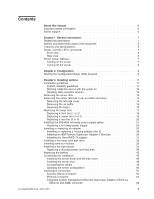
Keyboard connector 53 Parallel port connector 53 Serial-port connectors 53 Universal Serial Bus connectors 54 Video connector 54 Chapter 4. Service replaceable units 55 Microprocessor removal 56 Thermal grease 58 Operator information panel (external LED card 59 Diagnostics panel card 61 Power reset card 62 Diskette drive 63 CD-ROM drive 64 Hard disk drive backplane 65 Power supply cage assembly 66 Center-fan and adapter-support bracket 67 Center-fan support bracket (dual fan guide 69 Adapter-support bracket 70 Front fan housing (PCI fan guide 72 Front USB connector assembly 73 Switch card assembly 74 System board 76 System-board internal connectors 78 System-board internal cable connectors 79 System-board switches and jumpers 80 System-board external connectors 82 System-board LEDs 83 Light path diagnostics panel 84 Chapter 5. Diagnostics 87 General checkout 87 Checkout procedure 88 Diagnostic tools overview 89 POST error logs 90 Viewing error logs from the Configuration/Setup Utility program 90 Viewing error logs from the diagnostic programs 90 Diagnostic programs, error codes and messages 91 Diagnostic text message format 91 Starting the diagnostic programs 92 Light path diagnostics 93 Power-supply LEDs 95 Updating the BMC firmware 95 Resetting the BMC firmware 96 Small computer system interface messages 97 Recovering the BIOS code 97 Erasing a lost or forgotten password (clearing CMOS memory 99 Updating Remote Supervisor Adapter II SlimLine firmware 100 Power checkout 100 Troubleshooting the Ethernet controller 101 Network connection problems 101 Ethernet controller troubleshooting chart 101 Ethernet controller messages 102 Chapter 6. Symptom-to-FRU index 103 Beep symptoms 104 vi xSeries 236 Type 8841: Hardware Maintenance Manual and Troubleshooting Guide

  • 1
  • 2
  • 3
  • 4
  • 5
  • 6
  • 7
  • 8
  • 9
  • 10
  • 11
  • 12
  • 13
  • 14
  • 15
  • 16
  • 17
  • 18
  • 19
  • 20
  • 21
  • 22
  • 23
  • 24
  • 25
  • 26
  • 27
  • 28
  • 29
  • 30
  • 31
  • 32
  • 33
  • 34
  • 35
  • 36
  • 37
  • 38
  • 39
  • 40
  • 41
  • 42
  • 43
  • 44
  • 45
  • 46
  • 47
  • 48
  • 49
  • 50
  • 51
  • 52
  • 53
  • 54
  • 55
  • 56
  • 57
  • 58
  • 59
  • 60
  • 61
  • 62
  • 63
  • 64
  • 65
  • 66
  • 67
  • 68
  • 69
  • 70
  • 71
  • 72
  • 73
  • 74
  • 75
  • 76
  • 77
  • 78
  • 79
  • 80
  • 81
  • 82
  • 83
  • 84
  • 85
  • 86
  • 87
  • 88
  • 89
  • 90
  • 91
  • 92
  • 93
  • 94
  • 95
  • 96
  • 97
  • 98
  • 99
  • 100
  • 101
  • 102
  • 103
  • 104
  • 105
  • 106
  • 107
  • 108
  • 109
  • 110
  • 111
  • 112
  • 113
  • 114
  • 115
  • 116
  • 117
  • 118
  • 119
  • 120
  • 121
  • 122
  • 123
  • 124
  • 125
  • 126
  • 127
  • 128
  • 129
  • 130
  • 131
  • 132
  • 133
  • 134
  • 135
  • 136
  • 137
  • 138
  • 139
  • 140
  • 141
  • 142
  • 143
  • 144
  • 145
  • 146
  • 147
  • 148
  • 149
  • 150
  • 151
  • 152
  • 153
  • 154
  • 155
  • 156
  • 157
  • 158
  • 159
  • 160
  • 161
  • 162
  • 163
  • 164
  • 165
  • 166
  • 167
  • 168
  • 169
  • 170
  • 171
  • 172
  • 173
  • 174
  • 175
  • 176
  • 177
  • 178
  • 179
  • 180
  • 181
  • 182
  • 183
  • 184
  • 185
  • 186
  • 187
  • 188
  • 189
  • 190
  • 191
  • 192
  • 193
  • 194
  • 195
  • 196
  • 197
  • 198
  • 199
  • 200
  • 201
  • 202
  • 203
  • 204
  • 205
  • 206
  • 207
  • 208
  • 209
  • 210

Keyboard
connector
.
.
.
.
.
.
.
.
.
.
.
.
.
.
.
.
.
.
.
.
.
. 53
Parallel
port
connector
.
.
.
.
.
.
.
.
.
.
.
.
.
.
.
.
.
.
.
.
. 53
Serial-port
connectors
.
.
.
.
.
.
.
.
.
.
.
.
.
.
.
.
.
.
.
.
. 53
Universal
Serial
Bus
connectors
.
.
.
.
.
.
.
.
.
.
.
.
.
.
.
.
. 54
Video
connector
.
.
.
.
.
.
.
.
.
.
.
.
.
.
.
.
.
.
.
.
.
.
. 54
Chapter
4.
Service
replaceable
units
.
.
.
.
.
.
.
.
.
.
.
.
.
.
.
. 55
Microprocessor
removal
.
.
.
.
.
.
.
.
.
.
.
.
.
.
.
.
.
.
.
.
. 56
Thermal
grease
.
.
.
.
.
.
.
.
.
.
.
.
.
.
.
.
.
.
.
.
.
.
.
.
. 58
Operator
information
panel
(external
LED
card)
.
.
.
.
.
.
.
.
.
.
.
.
. 59
Diagnostics
panel
card
.
.
.
.
.
.
.
.
.
.
.
.
.
.
.
.
.
.
.
.
.
. 61
Power
reset
card
.
.
.
.
.
.
.
.
.
.
.
.
.
.
.
.
.
.
.
.
.
.
.
. 62
Diskette
drive
.
.
.
.
.
.
.
.
.
.
.
.
.
.
.
.
.
.
.
.
.
.
.
.
. 63
CD-ROM
drive
.
.
.
.
.
.
.
.
.
.
.
.
.
.
.
.
.
.
.
.
.
.
.
.
. 64
Hard
disk
drive
backplane
.
.
.
.
.
.
.
.
.
.
.
.
.
.
.
.
.
.
.
.
. 65
Power
supply
cage
assembly
.
.
.
.
.
.
.
.
.
.
.
.
.
.
.
.
.
.
. 66
Center-fan
and
adapter-support
bracket
.
.
.
.
.
.
.
.
.
.
.
.
.
.
.
. 67
Center-fan
support
bracket
(dual
fan
guide)
.
.
.
.
.
.
.
.
.
.
.
.
. 69
Adapter-support
bracket
.
.
.
.
.
.
.
.
.
.
.
.
.
.
.
.
.
.
.
. 70
Front
fan
housing
(PCI
fan
guide)
.
.
.
.
.
.
.
.
.
.
.
.
.
.
.
.
.
. 72
Front
USB
connector
assembly
.
.
.
.
.
.
.
.
.
.
.
.
.
.
.
.
.
.
. 73
Switch
card
assembly
.
.
.
.
.
.
.
.
.
.
.
.
.
.
.
.
.
.
.
.
.
. 74
System
board
.
.
.
.
.
.
.
.
.
.
.
.
.
.
.
.
.
.
.
.
.
.
.
.
. 76
System-board
internal
connectors
.
.
.
.
.
.
.
.
.
.
.
.
.
.
.
.
.
. 78
System-board
internal
cable
connectors
.
.
.
.
.
.
.
.
.
.
.
.
.
.
.
. 79
System-board
switches
and
jumpers
.
.
.
.
.
.
.
.
.
.
.
.
.
.
.
.
. 80
System-board
external
connectors
.
.
.
.
.
.
.
.
.
.
.
.
.
.
.
.
.
. 82
System-board
LEDs
.
.
.
.
.
.
.
.
.
.
.
.
.
.
.
.
.
.
.
.
.
.
. 83
Light
path
diagnostics
panel
.
.
.
.
.
.
.
.
.
.
.
.
.
.
.
.
.
.
.
. 84
Chapter
5.
Diagnostics
.
.
.
.
.
.
.
.
.
.
.
.
.
.
.
.
.
.
.
.
. 87
General
checkout
.
.
.
.
.
.
.
.
.
.
.
.
.
.
.
.
.
.
.
.
.
.
.
. 87
Checkout
procedure
.
.
.
.
.
.
.
.
.
.
.
.
.
.
.
.
.
.
.
.
.
.
. 88
Diagnostic
tools
overview
.
.
.
.
.
.
.
.
.
.
.
.
.
.
.
.
.
.
.
.
. 89
POST
error
logs
.
.
.
.
.
.
.
.
.
.
.
.
.
.
.
.
.
.
.
.
.
.
.
. 90
Viewing
error
logs
from
the
Configuration/Setup
Utility
program
.
.
.
.
.
. 90
Viewing
error
logs
from
the
diagnostic
programs
.
.
.
.
.
.
.
.
.
.
. 90
Diagnostic
programs,
error
codes
and
messages
.
.
.
.
.
.
.
.
.
.
.
. 91
Diagnostic
text
message
format
.
.
.
.
.
.
.
.
.
.
.
.
.
.
.
.
.
. 91
Starting
the
diagnostic
programs
.
.
.
.
.
.
.
.
.
.
.
.
.
.
.
.
. 92
Light
path
diagnostics
.
.
.
.
.
.
.
.
.
.
.
.
.
.
.
.
.
.
.
.
.
. 93
Power-supply
LEDs
.
.
.
.
.
.
.
.
.
.
.
.
.
.
.
.
.
.
.
.
.
.
. 95
Updating
the
BMC
firmware
.
.
.
.
.
.
.
.
.
.
.
.
.
.
.
.
.
.
.
. 95
Resetting
the
BMC
firmware
.
.
.
.
.
.
.
.
.
.
.
.
.
.
.
.
.
.
.
. 96
Small
computer
system
interface
messages
.
.
.
.
.
.
.
.
.
.
.
.
.
. 97
Recovering
the
BIOS
code
.
.
.
.
.
.
.
.
.
.
.
.
.
.
.
.
.
.
.
. 97
Erasing
a
lost
or
forgotten
password
(clearing
CMOS
memory)
.
.
.
.
.
.
. 99
Updating
Remote
Supervisor
Adapter
II
SlimLine
firmware
.
.
.
.
.
.
.
. 100
Power
checkout
.
.
.
.
.
.
.
.
.
.
.
.
.
.
.
.
.
.
.
.
.
.
.
. 100
Troubleshooting
the
Ethernet
controller
.
.
.
.
.
.
.
.
.
.
.
.
.
.
. 101
Network
connection
problems
.
.
.
.
.
.
.
.
.
.
.
.
.
.
.
.
.
. 101
Ethernet
controller
troubleshooting
chart
.
.
.
.
.
.
.
.
.
.
.
.
.
. 101
Ethernet
controller
messages
.
.
.
.
.
.
.
.
.
.
.
.
.
.
.
.
.
. 102
Chapter
6.
Symptom-to-FRU
index
.
.
.
.
.
.
.
.
.
.
.
.
.
.
.
. 103
Beep
symptoms
.
.
.
.
.
.
.
.
.
.
.
.
.
.
.
.
.
.
.
.
.
.
.
. 104
vi
xSeries
236
Type
8841:
Hardware
Maintenance
Manual
and
Troubleshooting
Guide