IBM 88410EU User Manual - Page 104
particular
 |
View all IBM 88410EU manuals
Add to My Manuals
Save this manual to your list of manuals |
Page 104 highlights
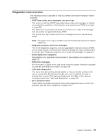
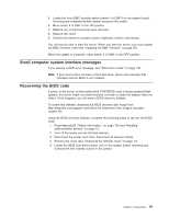
1 POWER SUPPLY 2 CONFIG TEMP REMIND MEMORY DASD/ RAID FAN CPU S_ERR VRM PCI BUS SERVICE NMI PROCESSOR BUS 3. Once you know the general type of error and the general location of the component involved, the next step is to check the system service label on the outside of the server. This label gives an overview of internal components that correspond to many of the LEDs on the light path diagnostics panel and can help to view lit LEDs inside the server. Note: Some of the LEDs on the light path diagnostics panel will not have a corresponding LED lit on the system board. For example: v LEDs for the power supplies, fans, and hard disk drives are located on or near the individual component. v Some error conditions are corrected by taking an action not related to one particular component; see step 5. 4. If the lit LED on the light path diagnostics panel refers to a specific internal component as indicated in step 3, look on the system board for lit error LEDs (see "System-board LEDs" on page 83). For example, a microprocessor error will light the LED next to the failing microprocessor. The error LEDs on the system board will only be lit when there is power to the server. To view them, read "Working inside the server with the power on" on page 12; then, remove the cover and look for any lit error LEDs. If the lit LED on the light path diagnostics panel does not refer to a specific internal component, continue with step 5. 5. Go to the table at "Light path diagnostic errors" on page 114 and find the entry for the associated lit LED; then, replace the indicated component or take the indicated action. Notes: v The system-error log and the BMC log might contain additional information that will be helpful before replacing a component. v If an LED on the light path diagnostics panel is lit and the system-error LED is not lit, there is probably an LED problem. Run LED diagnostics. 94 xSeries 236 Type 8841: Hardware Maintenance Manual and Troubleshooting Guide
-
 1
1 -
2
-
3
-
4
-
5
-
6
-
7
-
8
-
9
-
10
-
11
-
12
-
13
-
14
-
15
-
16
-
17
-
18
-
19
-
20
-
21
-
22
-
23
-
24
-
25
-
26
-
27
-
28
-
29
-
30
-
31
-
32
-
33
-
34
-
35
-
36
-
37
-
38
-
39
-
40
-
41
-
42
-
43
-
44
-
45
-
46
-
47
-
48
-
49
-
50
-
51
-
52
-
53
-
54
-
55
-
56
-
57
-
58
-
59
-
60
-
61
-
62
-
63
-
64
-
65
-
66
-
67
-
68
-
69
-
70
-
71
-
72
-
73
-
74
-
75
-
76
-
77
-
78
-
79
-
80
-
81
-
82
-
83
-
84
-
85
-
86
-
87
-
88
-
89
-
90
-
91
-
92
-
93
-
94
-
95
-
96
-
97
-
98
-
 99
99 -
 100
100 -
 101
101 -
 102
102 -
 103
103 -
 104
104 -
 105
105 -
 106
106 -
 107
107 -
 108
108 -
 109
109 -
110
-
111
-
112
-
113
-
114
-
115
-
116
-
117
-
118
-
119
-
120
-
121
-
122
-
123
-
124
-
125
-
126
-
127
-
128
-
129
-
130
-
131
-
132
-
133
-
134
-
135
-
136
-
137
-
138
-
139
-
140
-
141
-
142
-
143
-
144
-
145
-
146
-
147
-
148
-
149
-
150
-
151
-
152
-
153
-
154
-
155
-
156
-
157
-
158
-
159
-
160
-
161
-
162
-
163
-
164
-
165
-
166
-
167
-
168
-
169
-
170
-
171
-
172
-
173
-
174
-
175
-
176
-
177
-
178
-
179
-
180
-
181
-
182
-
183
-
184
-
185
-
186
-
187
-
188
-
189
-
190
-
191
-
192
-
193
-
194
-
195
-
196
-
197
-
198
-
199
-
200
-
201
-
202
-
203
-
204
-
205
-
206
-
207
-
208
-
209
-
210
 |
 |
