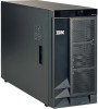
IBM 88410EU User Manual - Page 84
Switch, assembly
 |
View all IBM 88410EU manuals
Add to My Manuals
Save this manual to your list of manuals |
Page 84 highlights
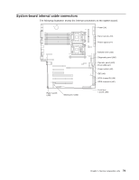
5. Disconnect and remove adapters and spacers (see "Installing or replacing an adapter" on page 25). 6. Remove the central fan and adapter-support bracket (see "Center-fan and adapter-support bracket" on page 67). 7. Remove the air baffle. 8. Disconnect the front USB cable from the system board (J41). 9. Use a Phillips screwdriver to remove the mounting screw from the front of the server; then, remove the USB cable from the server. To replace the front USB connector assembly, reverse the previous steps, threading the cable carefully. Switch card assembly Complete the following steps to remove the switch card assembly. Note: v Read "Installation guidelines" on page 11. v Read Appendix B, "Safety information," on page 153. v Read "Handling static-sensitive devices" on page 12. 1. Turn off the server. 2. Disconnect all external cables and power cords from the back of the server. 3. Remove the server cover (see "Removing the left-side cover" on page 14). 4. Remove all adapters and spacers (see "Installing or replacing an adapter" on page 25). 5. Disconnect the switch card cable from the system board. 74 xSeries 236 Type 8841: Hardware Maintenance Manual and Troubleshooting Guide
-
 1
1 -
2
-
3
-
4
-
5
-
6
-
7
-
8
-
9
-
10
-
11
-
12
-
13
-
14
-
15
-
16
-
17
-
18
-
19
-
20
-
21
-
22
-
23
-
24
-
25
-
26
-
27
-
28
-
29
-
30
-
31
-
32
-
33
-
34
-
35
-
36
-
37
-
38
-
39
-
40
-
41
-
42
-
43
-
44
-
45
-
46
-
47
-
48
-
49
-
50
-
51
-
52
-
53
-
54
-
55
-
56
-
57
-
58
-
59
-
60
-
61
-
62
-
63
-
64
-
65
-
66
-
67
-
68
-
69
-
70
-
71
-
72
-
73
-
74
-
75
-
76
-
77
-
78
-
 79
79 -
 80
80 -
 81
81 -
 82
82 -
 83
83 -
 84
84 -
 85
85 -
 86
86 -
 87
87 -
 88
88 -
 89
89 -
90
-
91
-
92
-
93
-
94
-
95
-
96
-
97
-
98
-
99
-
100
-
101
-
102
-
103
-
104
-
105
-
106
-
107
-
108
-
109
-
110
-
111
-
112
-
113
-
114
-
115
-
116
-
117
-
118
-
119
-
120
-
121
-
122
-
123
-
124
-
125
-
126
-
127
-
128
-
129
-
130
-
131
-
132
-
133
-
134
-
135
-
136
-
137
-
138
-
139
-
140
-
141
-
142
-
143
-
144
-
145
-
146
-
147
-
148
-
149
-
150
-
151
-
152
-
153
-
154
-
155
-
156
-
157
-
158
-
159
-
160
-
161
-
162
-
163
-
164
-
165
-
166
-
167
-
168
-
169
-
170
-
171
-
172
-
173
-
174
-
175
-
176
-
177
-
178
-
179
-
180
-
181
-
182
-
183
-
184
-
185
-
186
-
187
-
188
-
189
-
190
-
191
-
192
-
193
-
194
-
195
-
196
-
197
-
198
-
199
-
200
-
201
-
202
-
203
-
204
-
205
-
206
-
207
-
208
-
209
-
210
 |
 |
