IBM 88410EU User Manual - Page 130
Management
 |
View all IBM 88410EU manuals
Add to My Manuals
Save this manual to your list of manuals |
Page 130 highlights
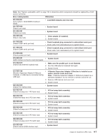
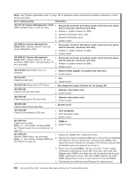
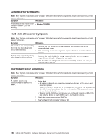
Note: See "System replaceable units" on page 144 to determine which components should be replaced by a field service technician. Error code/symptom FRU/action 166-407-001 System Management: Failed 1. Disconnect all server and option power cords from the server, (BMC indicates failure in I2C bus test.) wait 30 seconds, reconnect, and retry. 2. Reflash or update firmware for BMC. 3. Operator information panel cable. 4. Operator information panel. 5. System board. 166-NNN-001 System Management: Failed (BMC indicates failure in self test where NNN=300 to 320.) 1. Disconnect all server and option power cords from the server, wait 30 seconds, reconnect, and retry. 2. Reflash or update firmware for BMC. 3. System board. 166-NNN-001 System Management: 1. Disconnect all server and option power cords from the server, Failed (BMC indicates failure in I2C bus wait 30 seconds, reconnect, and retry. test where NNN=400 to 420 (excluding 412, 414, and 415).) 2. Reflash or update firmware for BMC. 3. System board. 180-197-000 (SCSI ASPI driver not installed) 1. Remove RAID adapter, if installed, and rerun test. 2. System board. 180-361-003 (Failed fan LED test) 1. Fan 2. System board 180-XXX-000 (Diagnostics LED failure) v Run diagnostics panel LED test for the failing LED. 180-XXX-001 (Failed front LED panel test) 1. Operator information card 2. System board 180-XXX-002 (Failed diagnostics LED panel test) 1. Operator information card 2. System board 180-XXX-003 (Failed system board LED test) v System board 180-XXX-005 (Failed SCSI backplane LED test) 1. SCSI backplane 2. SCSI backplane cable 3. System board 201-XXX-0nn (Failed memory test) Note: nn = slot number of failing DIMM; see "System-board internal connectors" on page 78. 1. DIMM nn 2. System board 201-XXX-n99 1. Reseat the DIMMs; then, restart the server. (Multiple DIMM failure, see error text) Note: n = slot number of failing DIMM pair; see Table 2 on page 33. 2. Remove the lowest-numbered DIMM pair of those that are identified and replace it with an identical pair of known good DIMMs; then, restart the server. Repeat as necessary. If the failures continue after all identified pairs are replaced, go to step 4. 3. Return the removed DIMMs, one pair at a time, to their original connectors, restarting the server after each pair, until a pair fails. Replace each DIMM in the failed pair with an identical known good DIMM, restarting the server after each DIMM. Replace the failed DIMM. Repeat step 3 until you have tested all removed DIMMs. 4. (Trained service technician only) Replace the system board. 120 xSeries 236 Type 8841: Hardware Maintenance Manual and Troubleshooting Guide
-
 1
1 -
2
-
3
-
4
-
5
-
6
-
7
-
8
-
9
-
10
-
11
-
12
-
13
-
14
-
15
-
16
-
17
-
18
-
19
-
20
-
21
-
22
-
23
-
24
-
25
-
26
-
27
-
28
-
29
-
30
-
31
-
32
-
33
-
34
-
35
-
36
-
37
-
38
-
39
-
40
-
41
-
42
-
43
-
44
-
45
-
46
-
47
-
48
-
49
-
50
-
51
-
52
-
53
-
54
-
55
-
56
-
57
-
58
-
59
-
60
-
61
-
62
-
63
-
64
-
65
-
66
-
67
-
68
-
69
-
70
-
71
-
72
-
73
-
74
-
75
-
76
-
77
-
78
-
79
-
80
-
81
-
82
-
83
-
84
-
85
-
86
-
87
-
88
-
89
-
90
-
91
-
92
-
93
-
94
-
95
-
96
-
97
-
98
-
99
-
100
-
101
-
102
-
103
-
104
-
105
-
106
-
107
-
108
-
109
-
110
-
111
-
112
-
113
-
114
-
115
-
116
-
117
-
118
-
119
-
120
-
121
-
122
-
123
-
124
-
 125
125 -
 126
126 -
 127
127 -
 128
128 -
 129
129 -
 130
130 -
 131
131 -
 132
132 -
 133
133 -
 134
134 -
 135
135 -
136
-
137
-
138
-
139
-
140
-
141
-
142
-
143
-
144
-
145
-
146
-
147
-
148
-
149
-
150
-
151
-
152
-
153
-
154
-
155
-
156
-
157
-
158
-
159
-
160
-
161
-
162
-
163
-
164
-
165
-
166
-
167
-
168
-
169
-
170
-
171
-
172
-
173
-
174
-
175
-
176
-
177
-
178
-
179
-
180
-
181
-
182
-
183
-
184
-
185
-
186
-
187
-
188
-
189
-
190
-
191
-
192
-
193
-
194
-
195
-
196
-
197
-
198
-
199
-
200
-
201
-
202
-
203
-
204
-
205
-
206
-
207
-
208
-
209
-
210
 |
 |
