IBM 88410EU User Manual - Page 77
Center-fan, adapter-support, bracket
 |
View all IBM 88410EU manuals
Add to My Manuals
Save this manual to your list of manuals |
Page 77 highlights
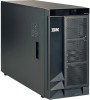
1 2 5. From the rear of the server, remove the two screws at each side of the power supply cage. 6. Gently pull the power supply cage from the server, making sure the cables do not snag on the chassis or system board. Note: You might need to insert the blade of a screwdriver behind one corner of the power supply cage to begin moving it. Center-fan and adapter-support bracket Note: v Read "Installation guidelines" on page 11. v Read Appendix B, "Safety information," on page 153. v Read "Handling static-sensitive devices" on page 12. When working with some options, you must first remove the center-fan and or adapter-support bracket to access certain components or connectors on the system board. Note: The adapter-support bracket is attached to the center-fan bracket. Both brackets can be removed and installed together as a single unit or individually. See "Center-fan support bracket (dual fan guide)" on page 69 or "Adapter-support bracket" on page 70 for instructions on how to remove these support brackets separately. Chapter 4. Service replaceable units 67
-
 1
1 -
2
-
3
-
4
-
5
-
6
-
7
-
8
-
9
-
10
-
11
-
12
-
13
-
14
-
15
-
16
-
17
-
18
-
19
-
20
-
21
-
22
-
23
-
24
-
25
-
26
-
27
-
28
-
29
-
30
-
31
-
32
-
33
-
34
-
35
-
36
-
37
-
38
-
39
-
40
-
41
-
42
-
43
-
44
-
45
-
46
-
47
-
48
-
49
-
50
-
51
-
52
-
53
-
54
-
55
-
56
-
57
-
58
-
59
-
60
-
61
-
62
-
63
-
64
-
65
-
66
-
67
-
68
-
69
-
70
-
71
-
 72
72 -
 73
73 -
 74
74 -
 75
75 -
 76
76 -
 77
77 -
 78
78 -
 79
79 -
 80
80 -
 81
81 -
 82
82 -
83
-
84
-
85
-
86
-
87
-
88
-
89
-
90
-
91
-
92
-
93
-
94
-
95
-
96
-
97
-
98
-
99
-
100
-
101
-
102
-
103
-
104
-
105
-
106
-
107
-
108
-
109
-
110
-
111
-
112
-
113
-
114
-
115
-
116
-
117
-
118
-
119
-
120
-
121
-
122
-
123
-
124
-
125
-
126
-
127
-
128
-
129
-
130
-
131
-
132
-
133
-
134
-
135
-
136
-
137
-
138
-
139
-
140
-
141
-
142
-
143
-
144
-
145
-
146
-
147
-
148
-
149
-
150
-
151
-
152
-
153
-
154
-
155
-
156
-
157
-
158
-
159
-
160
-
161
-
162
-
163
-
164
-
165
-
166
-
167
-
168
-
169
-
170
-
171
-
172
-
173
-
174
-
175
-
176
-
177
-
178
-
179
-
180
-
181
-
182
-
183
-
184
-
185
-
186
-
187
-
188
-
189
-
190
-
191
-
192
-
193
-
194
-
195
-
196
-
197
-
198
-
199
-
200
-
201
-
202
-
203
-
204
-
205
-
206
-
207
-
208
-
209
-
210
 |
 |
