IBM HS12 Service Guide - Page 140
Viewing the light path diagnostics LEDs, Memory modules DIMMs
 |
UPC - 883436037129
View all IBM HS12 manuals
Add to My Manuals
Save this manual to your list of manuals |
Page 140 highlights
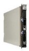
After you remove the blade server, you can press and hold the light path diagnostics switch for a maximum of 25 seconds to light the LEDs and locate the failing component. The following components have this feature: v Storage drives v Light path diagnostics panel v Microprocessors v Memory modules (DIMMs) Viewing the light path diagnostics LEDs Use this information to locate and identify the light path diagnostics LEDs. Before you work inside the blade server to view light path diagnostics LEDs, read "Safety" on page v and "Installation guidelines" on page 31. If an error occurs, view the light path diagnostics LEDs in the following order: 1. Look at the control panel on the front of the blade server (see "Blade server controls and LEDs" on page 7). v If the information LED is lit, it indicates that information about a suboptimal condition in the blade server is available in the BMC log or in the management-module event log. v If the blade-error LED is lit, it indicates that an error has occurred; view the light path diagnostics panel and LEDs to isolate the failing component. 2. To view the light path diagnostics panel and LEDs, complete the following steps: a. Remove the blade server from the BladeCenter unit. See "Removing the blade server from the BladeCenter unit" on page 33. b. Place the blade server on a flat, static-protective surface. c. Remove the cover from the blade server. See "Removing the blade server cover" on page 35. d. Press and hold the light path diagnostics switch to light the LEDs of the failing components in the blade server. The LEDs will remain lit for as long as you press the switch, to a maximum of 25 seconds. The following illustration shows the locations of the system-board error LEDs. 128 BladeCenter HS12 Type 8014, 8028 or 1916: Problem Determination and Service Guide
-
 1
1 -
2
-
3
-
4
-
5
-
6
-
7
-
8
-
9
-
10
-
11
-
12
-
13
-
14
-
15
-
16
-
17
-
18
-
19
-
20
-
21
-
22
-
23
-
24
-
25
-
26
-
27
-
28
-
29
-
30
-
31
-
32
-
33
-
34
-
35
-
36
-
37
-
38
-
39
-
40
-
41
-
42
-
43
-
44
-
45
-
46
-
47
-
48
-
49
-
50
-
51
-
52
-
53
-
54
-
55
-
56
-
57
-
58
-
59
-
60
-
61
-
62
-
63
-
64
-
65
-
66
-
67
-
68
-
69
-
70
-
71
-
72
-
73
-
74
-
75
-
76
-
77
-
78
-
79
-
80
-
81
-
82
-
83
-
84
-
85
-
86
-
87
-
88
-
89
-
90
-
91
-
92
-
93
-
94
-
95
-
96
-
97
-
98
-
99
-
100
-
101
-
102
-
103
-
104
-
105
-
106
-
107
-
108
-
109
-
110
-
111
-
112
-
113
-
114
-
115
-
116
-
117
-
118
-
119
-
120
-
121
-
122
-
123
-
124
-
125
-
126
-
127
-
128
-
129
-
130
-
131
-
132
-
133
-
134
-
 135
135 -
 136
136 -
 137
137 -
 138
138 -
 139
139 -
 140
140 -
 141
141 -
 142
142 -
 143
143 -
 144
144 -
 145
145 -
146
-
147
-
148
-
149
-
150
-
151
-
152
-
153
-
154
-
155
-
156
-
157
-
158
-
159
-
160
-
161
-
162
-
163
-
164
-
165
-
166
-
167
-
168
-
169
-
170
-
171
-
172
-
173
-
174
-
175
-
176
-
177
-
178
-
179
-
180
-
181
-
182
-
183
-
184
-
185
-
186
-
187
-
188
-
189
-
190
-
191
-
192
-
193
-
194
-
195
-
196
-
197
-
198
-
199
-
200
-
201
-
202
-
203
-
204
 |
 |
