IBM HS12 Service Guide - Page 52
Installing the bezel assembly, If you are instructed to return the bezel assembly
 |
UPC - 883436037129
View all IBM HS12 manuals
Add to My Manuals
Save this manual to your list of manuals |
Page 52 highlights
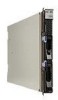
Bezel-assembly release Bezel-assembly release 1. Before you begin, read "Safety" on page v and "Installation guidelines" on page 31.. 2. If the blade server is installed in a BladeCenter unit, remove it (see "Removing the blade server from the BladeCenter unit" on page 33 for instructions). 3. Open the blade server cover (see "Removing the blade server cover" on page 35 for instructions). 4. If an optional expansion unit is installed, remove it (see "Removing an optional expansion unit" on page 37). 5. Press the bezel-assembly release on each side of the blade server and pull the bezel assembly away from the blade server approximately 1.2 cm (0.5 inch). 6. Disconnect the control panel cable from the control-panel connector. 7. Pull the bezel assembly away from the blade server. 8. If you are instructed to return the bezel assembly, follow all packaging instructions, and use any packaging materials for shipping that are supplied to you. Installing the bezel assembly Use this information to install a bezel assembly in the blade server. Note: 1. The following illustration shows how to install a bezel assembly in a blade server. 2. The illustrations in this document might differ slightly from your hardware. To install the bezel assembly, complete the following steps. Bezel-assembly release Bezel-assembly release 40 BladeCenter HS12 Type 8014, 8028 or 1916: Problem Determination and Service Guide
-
 1
1 -
2
-
3
-
4
-
5
-
6
-
7
-
8
-
9
-
10
-
11
-
12
-
13
-
14
-
15
-
16
-
17
-
18
-
19
-
20
-
21
-
22
-
23
-
24
-
25
-
26
-
27
-
28
-
29
-
30
-
31
-
32
-
33
-
34
-
35
-
36
-
37
-
38
-
39
-
40
-
41
-
42
-
43
-
44
-
45
-
46
-
 47
47 -
 48
48 -
 49
49 -
 50
50 -
 51
51 -
 52
52 -
 53
53 -
 54
54 -
 55
55 -
 56
56 -
 57
57 -
58
-
59
-
60
-
61
-
62
-
63
-
64
-
65
-
66
-
67
-
68
-
69
-
70
-
71
-
72
-
73
-
74
-
75
-
76
-
77
-
78
-
79
-
80
-
81
-
82
-
83
-
84
-
85
-
86
-
87
-
88
-
89
-
90
-
91
-
92
-
93
-
94
-
95
-
96
-
97
-
98
-
99
-
100
-
101
-
102
-
103
-
104
-
105
-
106
-
107
-
108
-
109
-
110
-
111
-
112
-
113
-
114
-
115
-
116
-
117
-
118
-
119
-
120
-
121
-
122
-
123
-
124
-
125
-
126
-
127
-
128
-
129
-
130
-
131
-
132
-
133
-
134
-
135
-
136
-
137
-
138
-
139
-
140
-
141
-
142
-
143
-
144
-
145
-
146
-
147
-
148
-
149
-
150
-
151
-
152
-
153
-
154
-
155
-
156
-
157
-
158
-
159
-
160
-
161
-
162
-
163
-
164
-
165
-
166
-
167
-
168
-
169
-
170
-
171
-
172
-
173
-
174
-
175
-
176
-
177
-
178
-
179
-
180
-
181
-
182
-
183
-
184
-
185
-
186
-
187
-
188
-
189
-
190
-
191
-
192
-
193
-
194
-
195
-
196
-
197
-
198
-
199
-
200
-
201
-
202
-
203
-
204
 |
 |
