Panasonic PT-DZ12000U Operating Instructions - Page 110
Using the, Remote 2 terminal
 |
UPC - 791871111550
View all Panasonic PT-DZ12000U manuals
Add to My Manuals
Save this manual to your list of manuals |
Page 110 highlights
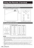
Using the Remote 2 terminal Using the REMOTE 2 terminal provided on the connection terminals of the main unit, it is possible to operate the projector from a control panel etc. furnished in a distant location where infrared remote control signal cannot be received. Example of a control panel layout Remote terminal External control Remote terminal/External control STANDBY ON LAMP RGB1 VIDEO RGB2 S-VIDEO Projector set up in a meeting room DVI-D Control panel located in a different room Pin assignments and control Be sure to short-circuit Pins 1 and 9 when controlling. D-Sub 9-pin (female) external appearance Names of terminals Open (H) Short (L) 1 GND GND 2 POWER OFF ON 3 RGB1 Other RGB1 4 RGB2 Other RGB2 5 VIDEO Other VIDEO 6 S-VIDEO Other S-VIDEO 7 DVI-D Other DVI-D 8 SHUTTER OFF ON 9 RST / SET Controlled by Controlled by remote control external contact Note • The above figure shows the pin assignment and control details when "REMOTE2 MODE" (p. 80) is "DEFAULT". When using "REMOTE2 MODE" with "USER", the pin assignment and control details are those set for "USER". • When pin 1 and pin 9 are short-circuited, the following buttons on the projector's control panel and on the remote control cannot be used. POWER button, SHUTTER button In addition, the RS-232C commands and network functions that correspond to these functions cannot be used either. • When pin 1 and pin 9 are short-circuited and then any one of pins 3 to 7 is short-circuited to pin 1, the following buttons on the projector's control panel and on the remote control cannot be used. POWER button, input selection buttons (RGB1, RGB2, DVI-D, AUX, VIDEO, S-VIDEO), SHUTTER button In addition, the RS-232C commands and network functions that correspond to these functions cannot be used either. 110 - ENGLISH
-
 1
1 -
2
-
3
-
4
-
5
-
6
-
7
-
8
-
9
-
10
-
11
-
12
-
13
-
14
-
15
-
16
-
17
-
18
-
19
-
20
-
21
-
22
-
23
-
24
-
25
-
26
-
27
-
28
-
29
-
30
-
31
-
32
-
33
-
34
-
35
-
36
-
37
-
38
-
39
-
40
-
41
-
42
-
43
-
44
-
45
-
46
-
47
-
48
-
49
-
50
-
51
-
52
-
53
-
54
-
55
-
56
-
57
-
58
-
59
-
60
-
61
-
62
-
63
-
64
-
65
-
66
-
67
-
68
-
69
-
70
-
71
-
72
-
73
-
74
-
75
-
76
-
77
-
78
-
79
-
80
-
81
-
82
-
83
-
84
-
85
-
86
-
87
-
88
-
89
-
90
-
91
-
92
-
93
-
94
-
95
-
96
-
97
-
98
-
99
-
100
-
101
-
102
-
103
-
104
-
 105
105 -
 106
106 -
 107
107 -
 108
108 -
 109
109 -
 110
110 -
 111
111 -
 112
112 -
 113
113 -
 114
114 -
 115
115 -
116
-
117
-
118
-
119
-
120
-
121
-
122
-
123
-
124
-
125
-
126
-
127
-
128
-
129
-
130
-
131
-
132
-
133
-
134
-
135
-
136
-
137
-
138
 |
 |
