Panasonic PT-DZ12000U Operating Instructions - Page 16
Connection terminals
 |
UPC - 791871111550
View all Panasonic PT-DZ12000U manuals
Add to My Manuals
Save this manual to your list of manuals |
Page 16 highlights
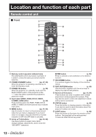
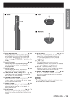
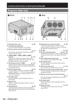
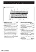
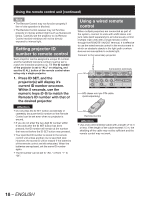
Location and function of each part (continued) „ Connection terminals 1 2 3 4 5 6 78 9 jk l 1 REMOTE1 lN/OUT terminal p. 18) When two or more main units are used in the system, they can be connected and controlled with a wired remote control cable (M3 jack). 2 REMOTE2 IN terminal p. 110) The user can remotely control the main unit by using an external control circuit to this terminal (D-SUB 9-pin female). 3 SERIAL IN terminalŋŋŋŋ (pp. 28-29, 80, 106-109) RS-232C compliant input terminal (switching necessary) to connect a PC and to externally control the main unit (D-SUB 9-pin female). 4 SERIAL IN terminalŋŋŋŋ (pp. 28-29, 80, 106-109) RS-422 compliant input terminal (switching necessary) to connect a PC and to externally control the main unit (D-SUB 9-pin female). 5 SERIAL OUT terminal pp. 29, 106-109) RS-422 compliant output terminal (switching necessary) to loop through signals from the Serial Input terminals (D-SUB 9-pin male). 6 LAN terminal (10BASE-T/100BASE-TX pp. 28-29, 93) The projector can be connected to a network and controlled through it's onboard web page. 7 VIDEO IN terminal p. 28) An input terminal for video signals. (BNC) 8 VIDEO OUT terminal p. 28) An output terminal (active through) for video signals. (BNC) 9 S-VIDEO IN terminal p. 28) An input terminal for S-video signals (Mini DIN 4-pin). This terminal complies with S1 signals and automatically toggles between 16:9 and 4:3 according to the size of input signals. j RGB (YPBPR) 1 IN terminal pp. 28, 29) A terminal to input RGB or YPBPR signals (3, 4 or 5-wire BNC). k RGB2 IN terminal p. 29) A terminal to input RGB or YPBPR signals (D-SUB 15-pin female). l DVI-D IN terminal pp. 28, 29) An input terminal for single-link DVI-D signals. 16 - ENGLISH
-
 1
1 -
2
-
3
-
4
-
5
-
6
-
7
-
8
-
9
-
10
-
 11
11 -
 12
12 -
 13
13 -
 14
14 -
 15
15 -
 16
16 -
 17
17 -
 18
18 -
 19
19 -
 20
20 -
 21
21 -
22
-
23
-
24
-
25
-
26
-
27
-
28
-
29
-
30
-
31
-
32
-
33
-
34
-
35
-
36
-
37
-
38
-
39
-
40
-
41
-
42
-
43
-
44
-
45
-
46
-
47
-
48
-
49
-
50
-
51
-
52
-
53
-
54
-
55
-
56
-
57
-
58
-
59
-
60
-
61
-
62
-
63
-
64
-
65
-
66
-
67
-
68
-
69
-
70
-
71
-
72
-
73
-
74
-
75
-
76
-
77
-
78
-
79
-
80
-
81
-
82
-
83
-
84
-
85
-
86
-
87
-
88
-
89
-
90
-
91
-
92
-
93
-
94
-
95
-
96
-
97
-
98
-
99
-
100
-
101
-
102
-
103
-
104
-
105
-
106
-
107
-
108
-
109
-
110
-
111
-
112
-
113
-
114
-
115
-
116
-
117
-
118
-
119
-
120
-
121
-
122
-
123
-
124
-
125
-
126
-
127
-
128
-
129
-
130
-
131
-
132
-
133
-
134
-
135
-
136
-
137
-
138
 |
 |
