Panasonic PT-DZ12000U Operating Instructions - Page 43
Basic Operation
 |
UPC - 791871111550
View all Panasonic PT-DZ12000U manuals
Add to My Manuals
Save this manual to your list of manuals |
Page 43 highlights
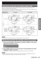
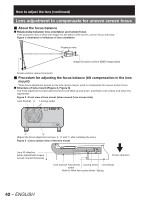
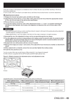
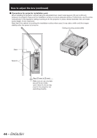
Basic Operation If the lens is heavy or the projector is installed so that it is tilted, the lens may be tilted, resulting in the focus becoming unbalanced. In such a case, refer to the figure 4 and table below, and follow the procedure below to perform adjustment. z Adjustment procedure 1 Display the internal test pattern grid, and defocus the image. 2 Adjust the lens focus till one or more sides of the grid comes into focus. Note the appropriate screws for the out-of-focus sides of the grid as described below. 3 Remove the lens cover and lens. 4 Loosen the locking screws for each of the adjustment screws a, b and c as needed, following the indications in the example. The screws to be adjusted correspond to the out-of-focus sides of the image. Attention • Be careful because turning a screw more than twice to loosen it will result in the spring becoming detached and the projector needing to be repaired. • Make adjustments in up to two places, and fully turn the screw clockwise in at least one place. 5 Reinstall the lens. The adjustment screws can be accessed through the lens flange. 6 Turn the adjustment screws (corresponding to the locking screws loosened in step 4) counterclockwise slightly till the out-of-focus image sides are in focus. (Turning the screws counterclockwise moves the lens bracket and tilts the lens toward the screen.) 7 Readjust the lens shift position with the remote if needed. 8 Refocus the image as in steps 1 and 2 above. Fine adjust the focus evenness as needed, as described in step 6. 9 When adjustment is complete, remove the lens and then tighten the locking screws. j Install the lens and lens cover. Tool to be used: Allen hex socket driver or Allen wrench (2.5 mm diagonal hexagon) An Allen wrench is supplied with the ET-D75LE6 and ET-D75LE8 optional lens. Figure 4 : Relation between the adjustment place and adjustment screw c V up b b c H left c a H right b a ac V bottom a ab Projector Screen Adjustment place: The place where the just-in-focus point is at the back. When optimal focus point is at front of screen for V up a Turn counterclockwise When optimal focus is at front of screen for V bottom When optimal focus is at front of screen for H left When optimal focus is at front of screen for H right b Turn counterclockwise Turn counterclockwise c Turn counterclockwise Turn counterclockwise ENGLISH - 43
-
 1
1 -
2
-
3
-
4
-
5
-
6
-
7
-
8
-
9
-
10
-
11
-
12
-
13
-
14
-
15
-
16
-
17
-
18
-
19
-
20
-
21
-
22
-
23
-
24
-
25
-
26
-
27
-
28
-
29
-
30
-
31
-
32
-
33
-
34
-
35
-
36
-
37
-
 38
38 -
 39
39 -
 40
40 -
 41
41 -
 42
42 -
 43
43 -
 44
44 -
 45
45 -
 46
46 -
 47
47 -
 48
48 -
49
-
50
-
51
-
52
-
53
-
54
-
55
-
56
-
57
-
58
-
59
-
60
-
61
-
62
-
63
-
64
-
65
-
66
-
67
-
68
-
69
-
70
-
71
-
72
-
73
-
74
-
75
-
76
-
77
-
78
-
79
-
80
-
81
-
82
-
83
-
84
-
85
-
86
-
87
-
88
-
89
-
90
-
91
-
92
-
93
-
94
-
95
-
96
-
97
-
98
-
99
-
100
-
101
-
102
-
103
-
104
-
105
-
106
-
107
-
108
-
109
-
110
-
111
-
112
-
113
-
114
-
115
-
116
-
117
-
118
-
119
-
120
-
121
-
122
-
123
-
124
-
125
-
126
-
127
-
128
-
129
-
130
-
131
-
132
-
133
-
134
-
135
-
136
-
137
-
138
 |
 |
