Panasonic PT-DZ12000U Operating Instructions - Page 66
Edge blending adjustment
 |
UPC - 791871111550
View all Panasonic PT-DZ12000U manuals
Add to My Manuals
Save this manual to your list of manuals |
Page 66 highlights
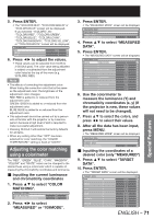
How to use ADVANCED MENU (continued) 2. Press ENTER. • The "CLAMP POSITION" screen will be displayed. CLAMP POSITION POSITION 1 ADJUST 3. Press ◄► to adjust. • The value changes from 0 to 255. • The optimal value for the clamp position adjustment If dark areas are crushed: The optimal value is the point where the dark area is best improved. If the dark areas are displayed in green: The optimal value is the point where the green areas become black and the crushing effect is rectified. Note • The clamp position can be adjusted only when the RGB signal input is applied with RGB1 and RGB2 IN. Edge blending adjustment The built-in edge blending feature allows multiple projector images to be seamlessly overlapped. 1. Press ▲▼ to select "EDGE BLENDING". CLAMP POSITION EDGE BLENDING FRAME DELAY OFF DEFAULT 2. Press ◄► to switch "EDGE BLENDING". • The setting will change as follows each time ◄► is pressed. OFF ON USER 4. Press ▲▼ to specify the area to be adjusted. • To blend the top edge: set "UPPER" to "ON". • To blend he bottom edge: set "LOWER" to "ON". • To blend the left edge: set "LEFT" to "ON". • To blend the right edge: set "RIGHT" to "ON". 5. Press ◄► to toggle "ON" and "OFF". 6. Press ◄► to adjust the overlap width and the starting point. „ To display the adjustment marker 7. Press ▲▼ to select "MARKER". RIGHT OFF MARKER OFF BRIGHT ADJUST 8. Press ◄► to select "ON". • A marker for adjusting the overlap position appears. The optimal point is the position where the red line of one frame overlaps the green line of the other frame. The blending widths of each projector must be set to the same value. Optimal blending cannot be achieved if the widths are different. The optimal point is where these lines overlap. • OFF: When the multi-screens are not going to be used. • ON: When the default linear blending ramps are sufficient. • USER: When a user-defined blending ramp is required. These ramps can be defined and uploaded to the projector through the RS-232 port. Consult your dealer for details. 3. Press ENTER. • The "EDGE BLENDING" screen will be displayed. EDGE BLENDING UPPER ON START 0 66 - ENGLISH Green line Red line 9. Press ▲▼ to select "BRIGHT ADJUST". RIGHT OFF MARKER OFF BRIGHT ADJUST
-
 1
1 -
2
-
3
-
4
-
5
-
6
-
7
-
8
-
9
-
10
-
11
-
12
-
13
-
14
-
15
-
16
-
17
-
18
-
19
-
20
-
21
-
22
-
23
-
24
-
25
-
26
-
27
-
28
-
29
-
30
-
31
-
32
-
33
-
34
-
35
-
36
-
37
-
38
-
39
-
40
-
41
-
42
-
43
-
44
-
45
-
46
-
47
-
48
-
49
-
50
-
51
-
52
-
53
-
54
-
55
-
56
-
57
-
58
-
59
-
60
-
 61
61 -
 62
62 -
 63
63 -
 64
64 -
 65
65 -
 66
66 -
 67
67 -
 68
68 -
 69
69 -
 70
70 -
 71
71 -
72
-
73
-
74
-
75
-
76
-
77
-
78
-
79
-
80
-
81
-
82
-
83
-
84
-
85
-
86
-
87
-
88
-
89
-
90
-
91
-
92
-
93
-
94
-
95
-
96
-
97
-
98
-
99
-
100
-
101
-
102
-
103
-
104
-
105
-
106
-
107
-
108
-
109
-
110
-
111
-
112
-
113
-
114
-
115
-
116
-
117
-
118
-
119
-
120
-
121
-
122
-
123
-
124
-
125
-
126
-
127
-
128
-
129
-
130
-
131
-
132
-
133
-
134
-
135
-
136
-
137
-
138
 |
 |
