Panasonic PT-DZ12000U Operating Instructions - Page 14
Projector Main Unit
 |
UPC - 791871111550
View all Panasonic PT-DZ12000U manuals
Add to My Manuals
Save this manual to your list of manuals |
Page 14 highlights
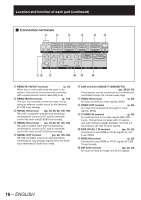
Location and function of each part (continued) Projector Main Unit „ Front „ Rear 1 2 3 45 6 n o 7 89j k l m pq rs 1 Projection lens cover p. 36) 2 Projection lens (optional) Lens for projecting images on the screen. 3 Remote control receiver window (front p. 17) This window receives the signal beam emitted from the remote control. 4 LAMP (LAMP1, LAMP2, LAMP3, LAMP4) monitor p. 111) These LEDS indicate the status of each lamp GREEN for "In Use", RED for "End-of-Life", and BLINKING RED for "Error Condition". 5 Temperature monitor (TEMP p. 111) These LEDs illuminate and flash to indicate lamp warmup intervals, abnormal internal temperatures, or cooling fan errors. 6 Power indicator lamp p. 37) The lamp lights in red when the MAIN POWER switch is turned to " l ". It turns to green when the POWER ON button of the remote control or the main unit is pressed. 7 Air intake vents During installation, ensure adequate airflow to these vents. 8 Burglar hook Attach a commercial burglar prevention cable to this hook port. 9 Adjustable feet p. 20) Use these feet to adjust the tilt of the projector. (Adjustable feet are provided at the front and rear, right and left.) j Projection lens cover lock button p. 36) Press these side buttons to unlock the lens cowling, pulling it forward to remove. Centering the lens first may ease removal. k Air filter p. 112) l Air filter cleaning monitor pp. 81, 112) This blinks blue while the air filter is being cleaned. It lights red when there is a problem with the air filter. m Filter cleaning unit fixing screw p. 112) This is used to secure the air filter cover. n Air exhaust vents During installation do not allow these vents to become blocked. o Lamp unit cover screw p. 115) This is used to secure the lamp unit cover. p Remote control receiver window (rear) ŋ (p. 17) This also receives the signal beam coming from the remote control. q Remote control receiver window (bottom p. 17) This also receives the signal beam coming from the remote control. r Air intake vents During installation, ensure adequate airflow to these vents. s Lamp unit cover p. 115) This hinged panel swings down for lamp replacement. 14 - ENGLISH
-
 1
1 -
2
-
3
-
4
-
5
-
6
-
7
-
8
-
 9
9 -
 10
10 -
 11
11 -
 12
12 -
 13
13 -
 14
14 -
 15
15 -
 16
16 -
 17
17 -
 18
18 -
 19
19 -
20
-
21
-
22
-
23
-
24
-
25
-
26
-
27
-
28
-
29
-
30
-
31
-
32
-
33
-
34
-
35
-
36
-
37
-
38
-
39
-
40
-
41
-
42
-
43
-
44
-
45
-
46
-
47
-
48
-
49
-
50
-
51
-
52
-
53
-
54
-
55
-
56
-
57
-
58
-
59
-
60
-
61
-
62
-
63
-
64
-
65
-
66
-
67
-
68
-
69
-
70
-
71
-
72
-
73
-
74
-
75
-
76
-
77
-
78
-
79
-
80
-
81
-
82
-
83
-
84
-
85
-
86
-
87
-
88
-
89
-
90
-
91
-
92
-
93
-
94
-
95
-
96
-
97
-
98
-
99
-
100
-
101
-
102
-
103
-
104
-
105
-
106
-
107
-
108
-
109
-
110
-
111
-
112
-
113
-
114
-
115
-
116
-
117
-
118
-
119
-
120
-
121
-
122
-
123
-
124
-
125
-
126
-
127
-
128
-
129
-
130
-
131
-
132
-
133
-
134
-
135
-
136
-
137
-
138
 |
 |
