Cisco 7912G Administration Guide - Page 62
Connecting the Cisco IP Phone to the Network
 |
UPC - 746320852409
View all Cisco 7912G manuals
Add to My Manuals
Save this manual to your list of manuals |
Page 62 highlights
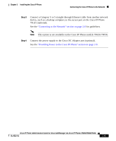
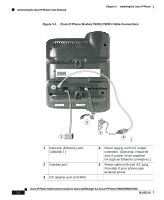
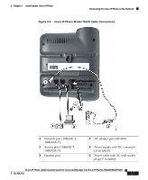
Connecting the Cisco IP Phone to the Network Chapter 3 Installing the Cisco IP Phone The following warnings apply when you use an external power supply. Warning This product relies on the building's installation for short-circuit (overcurrent) protection. Ensure that a fuse or circuit breaker no larger than 120 VAC, 15 A U.S. (240 VAC, 10 A international) is used on the phase conductors (all current-carrying conductors). Warning The device is designed to work with TN power systems. Warning The plug-socket combination must be accessible at all times because it serves as the main disconnecting device. Connecting the Cisco IP Phone to the Network You must connect the Cisco IP Phone to the network and to a power source before using it. See Figure 3-1 and Figure 3-2 for graphical overviews of the procedures that follow. To install a Cisco IP Phone, perform these steps. Procedure Step 1 Step 2 Connect a Category 3 or 5 straight-through Ethernet cable from the switch to the network port on the phone. See the "Connecting to the Network" section on page 2-8 for guidelines. Each Cisco IP Phone ships with one Ethernet cable in the box. Connect the handset to its port. Cisco IP Phone Administration Guide for Cisco CallManager 3.3, Cisco IP Phones 7902G/7905G/7912G 3-4 OL-6313-01
-
 1
1 -
2
-
3
-
4
-
5
-
6
-
7
-
8
-
9
-
10
-
11
-
12
-
13
-
14
-
15
-
16
-
17
-
18
-
19
-
20
-
21
-
22
-
23
-
24
-
25
-
26
-
27
-
28
-
29
-
30
-
31
-
32
-
33
-
34
-
35
-
36
-
37
-
38
-
39
-
40
-
41
-
42
-
43
-
44
-
45
-
46
-
47
-
48
-
49
-
50
-
51
-
52
-
53
-
54
-
55
-
56
-
 57
57 -
 58
58 -
 59
59 -
 60
60 -
 61
61 -
 62
62 -
 63
63 -
 64
64 -
 65
65 -
 66
66 -
 67
67 -
68
-
69
-
70
-
71
-
72
-
73
-
74
-
75
-
76
-
77
-
78
-
79
-
80
-
81
-
82
-
83
-
84
-
85
-
86
-
87
-
88
-
89
-
90
-
91
-
92
-
93
-
94
-
95
-
96
-
97
-
98
-
99
-
100
-
101
-
102
-
103
-
104
-
105
-
106
-
107
-
108
-
109
-
110
-
111
-
112
-
113
-
114
-
115
-
116
-
117
-
118
-
119
-
120
-
121
-
122
-
123
-
124
-
125
-
126
-
127
-
128
-
129
-
130
-
131
-
132
-
133
-
134
-
135
-
136
-
137
-
138
-
139
-
140
-
141
-
142
-
143
-
144
-
145
-
146
-
147
-
148
-
149
-
150
-
151
-
152
-
153
-
154
-
155
-
156
-
157
-
158
-
159
-
160
-
161
-
162
-
163
-
164
-
165
-
166
-
167
-
168
-
169
-
170
-
171
-
172
-
173
-
174
-
175
-
176
-
177
-
178
-
179
-
180
-
181
-
182
-
183
-
184
 |
 |