Epson LQ 1050 Technical Manual - Page 104
Cpumpd7810hg, Gae05a
 |
View all Epson LQ 1050 manuals
Add to My Manuals
Save this manual to your list of manuals |
Page 104 highlights
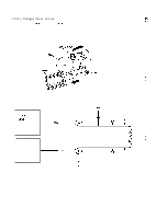
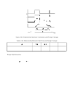
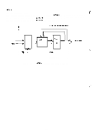
REV.-A 2.3.5.5 Printhead Control Circuit g ':4 $-,, Printing is controlled by the CPU (~PE78 10HG), gate array (E05A 15HA), nine drive transistors, and printhead. Print data output from the CPU is stored in the buffer of the E05A15HA gate array. The printhead drive pulse output from PC6 of the CPU enables the buffer is the gate array, and the 9 bits of print data stored in the buffer are output to turn on or off the printhead drive transistors so that the drive voltages are applied to the printhead coils. Figure 2-50 shows a block diagram of the printhead control circuit. CPU(MPD7810HG) Y (4B) P?7 PDO PC6 ANO L AN2 GA(E05A 15HA) 1 (3A) Buffer C3987X9 ---.r, -r \ - -- v ' 1' ) ' -D u') ~. = --- ---J GP +5 Printhead r-1 I I II I '!I ' -:" ' x I-- --I ...4 1 Vp Figure 2-50. Printhead Control Circuit Block Diagram 2-60
-
 1
1 -
2
-
3
-
4
-
5
-
6
-
7
-
8
-
9
-
10
-
11
-
12
-
13
-
14
-
15
-
16
-
17
-
18
-
19
-
20
-
21
-
22
-
23
-
24
-
25
-
26
-
27
-
28
-
29
-
30
-
31
-
32
-
33
-
34
-
35
-
36
-
37
-
38
-
39
-
40
-
41
-
42
-
43
-
44
-
45
-
46
-
47
-
48
-
49
-
50
-
51
-
52
-
53
-
54
-
55
-
56
-
57
-
58
-
59
-
60
-
61
-
62
-
63
-
64
-
65
-
66
-
67
-
68
-
69
-
70
-
71
-
72
-
73
-
74
-
75
-
76
-
77
-
78
-
79
-
80
-
81
-
82
-
83
-
84
-
85
-
86
-
87
-
88
-
89
-
90
-
91
-
92
-
93
-
94
-
95
-
96
-
97
-
98
-
 99
99 -
 100
100 -
 101
101 -
 102
102 -
 103
103 -
 104
104 -
 105
105 -
 106
106 -
 107
107 -
 108
108 -
 109
109 -
110
-
111
-
112
-
113
-
114
-
115
-
116
-
117
-
118
-
119
-
120
-
121
-
122
-
123
-
124
-
125
-
126
-
127
-
128
-
129
-
130
-
131
-
132
-
133
-
134
-
135
-
136
-
137
-
138
-
139
-
140
-
141
-
142
-
143
-
144
-
145
-
146
-
147
-
148
-
149
-
150
-
151
-
152
-
153
-
154
-
155
-
156
-
157
-
158
-
159
-
160
-
161
-
162
-
163
-
164
-
165
-
166
-
167
-
168
-
169
-
170
-
171
-
172
-
173
-
174
-
175
-
176
-
177
-
178
-
179
-
180
-
181
-
182
-
183
-
184
-
185
-
186
-
187
-
188
-
189
-
190
-
191
-
192
-
193
-
194
-
195
-
196
-
197
-
198
-
199
-
200
-
201
-
202
-
203
-
204
-
205
-
206
-
207
-
208
-
209
-
210
-
211
-
212
-
213
-
214
-
215
-
216
-
217
-
218
-
219
-
220
-
221
-
222
-
223
-
224
-
225
 |
 |
