Epson LQ 1050 Technical Manual - Page 179
Preventive Maintenance, 2 Lubrication And Adhesive Application
 |
View all Epson LQ 1050 manuals
Add to My Manuals
Save this manual to your list of manuals |
Page 179 highlights
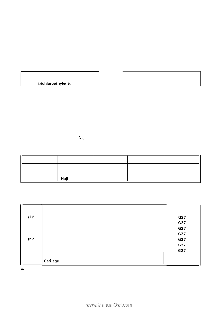
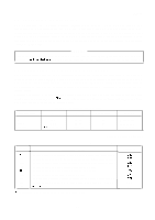
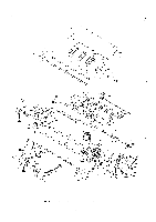
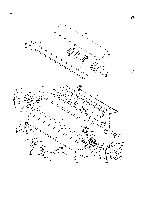
REV.-A 6.1 PREVENTIVE MAINTENANCE Proper maintenance is essential to maintain optimal printer performance for the longest possible period and to minimize malfunction frequency. Preventive maintenance includes regular cleaning of the case exterior, using alcohol, and occasional vacuuming of the mechanism interior to remove dust and paper particles. Following cleaning, refer to Section 6.2 to verify that the unit is adequately lubricated. Before returning the serviced printer to the consumer, inspect the springs, paper feed rollers, and the basic operation of the unit. WARNING Disconnect the printer from the power supply before performing maintenance. Do not use thinner, trichloroethylene, or ketone-based solvents on the plastic components of the printer. 6.2 LUBRICATION AND ADHESIVE APPLICATION EPSON recommends that the points illustrated in Figure 6-2 be lubricated according to the schedule listed in Table 6-2, with EPSON O-2 and G-27, which have been extensively tested and found to comply with the need of this printer (Refer to Table 6-1 for details of O-2 and G-27.). Be sure that the parts to be lubricated are clean before applying lubricant, and avoid excessive application, which may damage related parts. Adhesive application is necessary at the point indicated in Table 6-3 when the part is disassembled or replaced EPSON recommends Neji lock #2 (G) adhesive be applied to the point diagrammed in Figure 6-5. Avoid overview of excess to related parts. Table 6-1. Lubricants and Adhesive Classification Designation Capacity Availability Part No. Oil Grease Adhesive o-2 G-27 Neji lock #2 (g) 40 cc 40 gr 1000 gr E B7 10200001 E 6702700001 E B730200200 E: EPSON exclusive product Table 6-2. Lubrication Points (Refer to Figures 6-1 through 6-4.) Ref. No. Lubrication Point Lubricant (l)* Contact portion of carriage motor mounting plate and base frame ~ (2)* Contact portion of sub paper release lever and paper release lever (3)* Contact portion of tractor transmission gear and paper release lever (4)" Contact portion of paper holding lever R and shaft (5)* Contact portion of paper holding lever L and shaft (6)* Contact portion of loading lever and shaft (7)* Contact portion of head adjustment lever tab and holes of side frame L (8)* Contact portion of paper feed roller holder and paper feed roller (9)* Car;iage felt G27 G27 G27 G27 G27 G27 G27 G-27 02 *: Lubrication is necessary in the process of assembly. 6-1
-
 1
1 -
2
-
3
-
4
-
5
-
6
-
7
-
8
-
9
-
10
-
11
-
12
-
13
-
14
-
15
-
16
-
17
-
18
-
19
-
20
-
21
-
22
-
23
-
24
-
25
-
26
-
27
-
28
-
29
-
30
-
31
-
32
-
33
-
34
-
35
-
36
-
37
-
38
-
39
-
40
-
41
-
42
-
43
-
44
-
45
-
46
-
47
-
48
-
49
-
50
-
51
-
52
-
53
-
54
-
55
-
56
-
57
-
58
-
59
-
60
-
61
-
62
-
63
-
64
-
65
-
66
-
67
-
68
-
69
-
70
-
71
-
72
-
73
-
74
-
75
-
76
-
77
-
78
-
79
-
80
-
81
-
82
-
83
-
84
-
85
-
86
-
87
-
88
-
89
-
90
-
91
-
92
-
93
-
94
-
95
-
96
-
97
-
98
-
99
-
100
-
101
-
102
-
103
-
104
-
105
-
106
-
107
-
108
-
109
-
110
-
111
-
112
-
113
-
114
-
115
-
116
-
117
-
118
-
119
-
120
-
121
-
122
-
123
-
124
-
125
-
126
-
127
-
128
-
129
-
130
-
131
-
132
-
133
-
134
-
135
-
136
-
137
-
138
-
139
-
140
-
141
-
142
-
143
-
144
-
145
-
146
-
147
-
148
-
149
-
150
-
151
-
152
-
153
-
154
-
155
-
156
-
157
-
158
-
159
-
160
-
161
-
162
-
163
-
164
-
165
-
166
-
167
-
168
-
169
-
170
-
171
-
172
-
173
-
 174
174 -
 175
175 -
 176
176 -
 177
177 -
 178
178 -
 179
179 -
 180
180 -
 181
181 -
 182
182 -
 183
183 -
 184
184 -
185
-
186
-
187
-
188
-
189
-
190
-
191
-
192
-
193
-
194
-
195
-
196
-
197
-
198
-
199
-
200
-
201
-
202
-
203
-
204
-
205
-
206
-
207
-
208
-
209
-
210
-
211
-
212
-
213
-
214
-
215
-
216
-
217
-
218
-
219
-
220
-
221
-
222
-
223
-
224
-
225
 |
 |