Epson LQ 1050 Technical Manual - Page 57
E05A15HA gate array 3A
 |
View all Epson LQ 1050 manuals
Add to My Manuals
Save this manual to your list of manuals |
Page 57 highlights
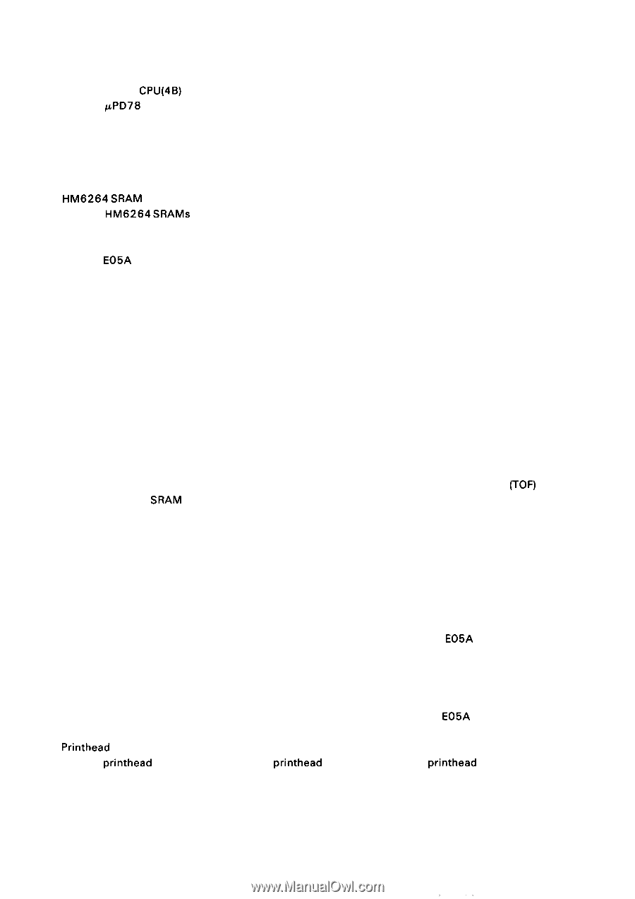
REV.-A The control circuit consists mainly of the following ICS: q p P D 7 8 1 0 H G CPU(4B) The KPD78 10HG CPU executes the program in the 27256 PROM (4A) and controls all of the printer operations. The CPU begins executing the program from address OOOOH upon receiving the reset signal. The CPU also reads the DIP switch and jumper settings and detects the states of the analog circuits. q 27256 PROM (4A) The 27256 PROM includes the control program (firmware) and character generators. q HM6264 SRAM (X 2) (5A/6A) The HM6264 SRAMS are external memories for the CPU. They are used as an input data buffer and line buffer for expanding data and as a working area for the program. (8K x 2 = 16K bytes) q E05A16G gate array (7A) The E05A 16GA gate array controls handshaking for parallel data (including the optional interface), the control panel, plunger, speed of the carriage motor, and reset signal. The gate array also generates Italic and Super/subscript characters so that command processing speed is improved and the load on the firmware is lightened. q E05A15HA gate array (3A) The E05A15HA gate array has address latch and address decode functions, and controls the memory. The gate array also controls the carriage and paper feed motors using the 2-channel automatic phase switching circuit. In addition, the gate array reads the states of the head data buffer, carriage home position sensor, paper end sensor, and release switch sensor. Other control circuits are as follows: q Reset circuit The reset circuit outputs the reset signal. The reset signal is sent to the CPU for the necessary time either when the printer power is turned on or when the I NIT signal is input from the host computer. q Memory back-up circuit The memory back-up circuit backs up the panel settings and data for the top-of-form (TOF) position stored in the SRAM (6A) when the printer power is turned off, so that the values will remain valid when the printer power is turned on again. The DC voltage supplied to this circuit is monitored, and power is supplied from the battery for back-up when the main-power voltage level drops. q Plunger drive circuit The plunger drive circuit drives the plunger using the plunger control signal. The plunger is controlled by switching the drive voltage on and off. ' Paper feed motor drive circuit The paper feed motor drive circuit drives the paper feed motor using the motor control signals. The paper feed motor is a 4-phase stepper motor. The rotation of the motor (position and speed) is controlled by outputting the phase switching signal generated by the E05A 15HA gate array and switching the common voltage (driving or holding). q Carriage motor drive circuit The carriage motor drive circuit drives the carriage motor using the carriage motor control signals. The carriage motor is a 4-phase stepper motor. The rotation of the motor (position and speed) is controlled by outputting the phase switching signal generated by the E05A 15HA gate array and switching the common voltage (driving or holding). q Printhead drive circuit The printhead drive circuit drives the printhead after expanding the printhead data. Data from the host computer is processed and expanded so that it is converted to dot data for one vertical row. Printing is executed by expanding the patterns for vertical rows as the carriage moves. 2-13
-
 1
1 -
2
-
3
-
4
-
5
-
6
-
7
-
8
-
9
-
10
-
11
-
12
-
13
-
14
-
15
-
16
-
17
-
18
-
19
-
20
-
21
-
22
-
23
-
24
-
25
-
26
-
27
-
28
-
29
-
30
-
31
-
32
-
33
-
34
-
35
-
36
-
37
-
38
-
39
-
40
-
41
-
42
-
43
-
44
-
45
-
46
-
47
-
48
-
49
-
50
-
51
-
 52
52 -
 53
53 -
 54
54 -
 55
55 -
 56
56 -
 57
57 -
 58
58 -
 59
59 -
 60
60 -
 61
61 -
 62
62 -
63
-
64
-
65
-
66
-
67
-
68
-
69
-
70
-
71
-
72
-
73
-
74
-
75
-
76
-
77
-
78
-
79
-
80
-
81
-
82
-
83
-
84
-
85
-
86
-
87
-
88
-
89
-
90
-
91
-
92
-
93
-
94
-
95
-
96
-
97
-
98
-
99
-
100
-
101
-
102
-
103
-
104
-
105
-
106
-
107
-
108
-
109
-
110
-
111
-
112
-
113
-
114
-
115
-
116
-
117
-
118
-
119
-
120
-
121
-
122
-
123
-
124
-
125
-
126
-
127
-
128
-
129
-
130
-
131
-
132
-
133
-
134
-
135
-
136
-
137
-
138
-
139
-
140
-
141
-
142
-
143
-
144
-
145
-
146
-
147
-
148
-
149
-
150
-
151
-
152
-
153
-
154
-
155
-
156
-
157
-
158
-
159
-
160
-
161
-
162
-
163
-
164
-
165
-
166
-
167
-
168
-
169
-
170
-
171
-
172
-
173
-
174
-
175
-
176
-
177
-
178
-
179
-
180
-
181
-
182
-
183
-
184
-
185
-
186
-
187
-
188
-
189
-
190
-
191
-
192
-
193
-
194
-
195
-
196
-
197
-
198
-
199
-
200
-
201
-
202
-
203
-
204
-
205
-
206
-
207
-
208
-
209
-
210
-
211
-
212
-
213
-
214
-
215
-
216
-
217
-
218
-
219
-
220
-
221
-
222
-
223
-
224
-
225
 |
 |