Epson LQ 1050 Technical Manual - Page 148
Tractor Assembly Phases
 |
View all Epson LQ 1050 manuals
Add to My Manuals
Save this manual to your list of manuals |
Page 148 highlights
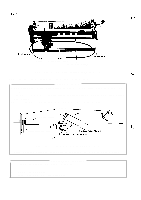
REV.-A 4.2.5.19 Push Tractor Unit Disassembly This section describes the removal of the tractor assembly (left). Since disassembled parts can be reassembled by using the removal procedures in reverse order, assembly procedures have been omitted. Step 1: Remove the shaft holder from the tractor mounting plate L. Step 2: Remove the CPS (0)(3 X 6) screw securing tractor mounting plate L to the tractor base frame. Step 3: Remove the HNO (4) nut securing the tractor guide shaft. Step 4: Remove the tractor side frame L. Step 5: Push the tractor lock lever upward, and remove the left sprocket assembly from the shafts. Tra
-
 1
1 -
2
-
3
-
4
-
5
-
6
-
7
-
8
-
9
-
10
-
11
-
12
-
13
-
14
-
15
-
16
-
17
-
18
-
19
-
20
-
21
-
22
-
23
-
24
-
25
-
26
-
27
-
28
-
29
-
30
-
31
-
32
-
33
-
34
-
35
-
36
-
37
-
38
-
39
-
40
-
41
-
42
-
43
-
44
-
45
-
46
-
47
-
48
-
49
-
50
-
51
-
52
-
53
-
54
-
55
-
56
-
57
-
58
-
59
-
60
-
61
-
62
-
63
-
64
-
65
-
66
-
67
-
68
-
69
-
70
-
71
-
72
-
73
-
74
-
75
-
76
-
77
-
78
-
79
-
80
-
81
-
82
-
83
-
84
-
85
-
86
-
87
-
88
-
89
-
90
-
91
-
92
-
93
-
94
-
95
-
96
-
97
-
98
-
99
-
100
-
101
-
102
-
103
-
104
-
105
-
106
-
107
-
108
-
109
-
110
-
111
-
112
-
113
-
114
-
115
-
116
-
117
-
118
-
119
-
120
-
121
-
122
-
123
-
124
-
125
-
126
-
127
-
128
-
129
-
130
-
131
-
132
-
133
-
134
-
135
-
136
-
137
-
138
-
139
-
140
-
141
-
142
-
 143
143 -
 144
144 -
 145
145 -
 146
146 -
 147
147 -
 148
148 -
 149
149 -
 150
150 -
 151
151 -
 152
152 -
 153
153 -
154
-
155
-
156
-
157
-
158
-
159
-
160
-
161
-
162
-
163
-
164
-
165
-
166
-
167
-
168
-
169
-
170
-
171
-
172
-
173
-
174
-
175
-
176
-
177
-
178
-
179
-
180
-
181
-
182
-
183
-
184
-
185
-
186
-
187
-
188
-
189
-
190
-
191
-
192
-
193
-
194
-
195
-
196
-
197
-
198
-
199
-
200
-
201
-
202
-
203
-
204
-
205
-
206
-
207
-
208
-
209
-
210
-
211
-
212
-
213
-
214
-
215
-
216
-
217
-
218
-
219
-
220
-
221
-
222
-
223
-
224
-
225
 |
 |

REV.-A
4.2.5.19 Push Tractor Unit Disassembly
This section describes the removal of the tractor assembly (left). Since disassembled parts can be
reassembled by using the removal procedures in reverse order,
assembly procedures have been
omitted.
Step 1:
Step 2:
Step 3:
Step 4:
Step 5:
Remove the shaft holder from the tractor mounting plate L.
Remove the CPS (0)(3 X 6) screw securing tractor mounting plate L to the tractor base frame.
Remove the HNO (4) nut securing the tractor guide shaft.
Remove the tractor side frame L.
Push the tractor lock lever upward, and remove the left sprocket assembly from the shafts.
&
Tractor Lock Lever
,Tractor
Assembly (left)
/
Tra<tor
A%
‘“6(7”*
Shaft
Holder
-.
.-.
.
------
Figure 4-50. Tractor Assembly (left) Removal
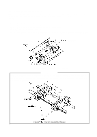
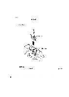
ASSEMBLY POINT
When mounting the tractor assemblies to the shafts, set them so that the marks on the right and
left tractor frames are at the same position. Make sure that the pins on the right and left tractor belts
are aligned in parallel.
Make
Figure
4-51,
Tractor Assembly Phases
4-35