Epson LQ 1050 Technical Manual - Page 131
REV.-A, Step6
 |
View all Epson LQ 1050 manuals
Add to My Manuals
Save this manual to your list of manuals |
Page 131 highlights
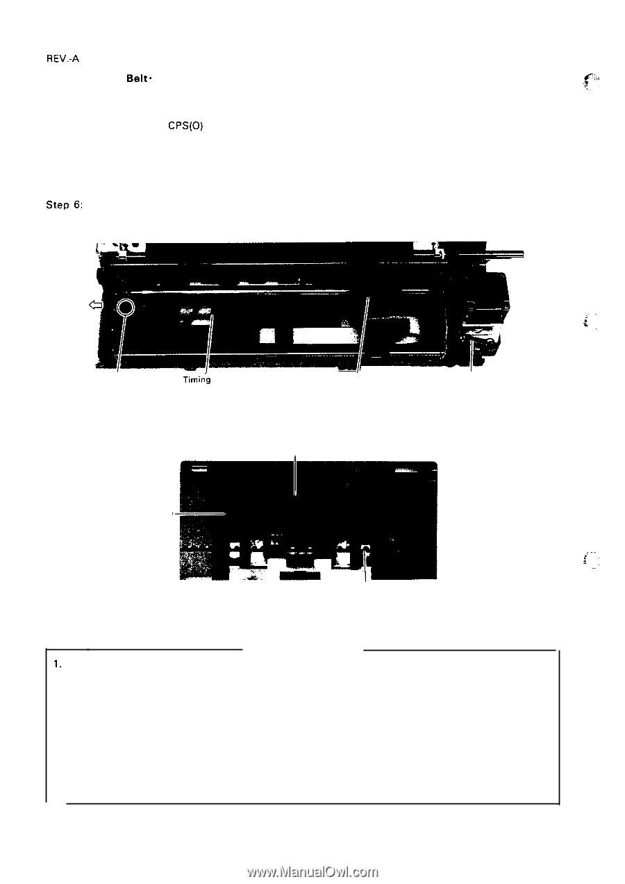
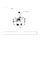
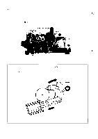
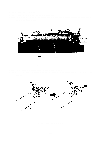
REV.-A 4.2.5.5 Timing Belt" Belt-Driven Pulley Removal S t e p l : Remove the printer mechanism (Refer to Section 4.2.5. 1.). Step2: Remove the timing-belt tension spring. Step3: Loosen the two CPS(0) (3 X 10) screws which fixing carriage motor mounting plate to the base frame. Step4: Pull the timing belt out from carriage motor pulley. Step5: Place the carriage over the notch in right side of the base frame, and release the engaged parts of the timing belt and carriage from the bottom side of the base frame. Step6: Remove the belt-driven pulley by moving it to the left, and remove the timing belt. ,,, ,. ~ .. Belt Driven Pulley Timin"g Belt Printhead Position Timing Belt Tension Spring Figure 4-22. Timing Belt Removal Engaged Part Carriage Bottom View Timing Belt ,, .. . . * r,.,.. Figure 4-23. Timing Belt Insertion ASSEMBLY POINTS 1. Verify that the timing belt runs around the belt-driven pulley and the belt-driving pulley of the carriage motor shaft. 2. Insert the timing belt firmly into the carriage, utilizing the notch in the base frame, in the same way as when removing it. After insertion, apply adhesive at the engaged parts of the carriage and the belt (Refer to Section 6.2, Lubrication and Adhesive Application.). Insert the belt until the undersurfaces of the belt mesh with the inserted parts of the carriage. 3. Hang the timing-belt tension spring on hooks for both base frame and carriage motor mounting plate. 4. Tighten the screws on the carriage motor mounting plate. - 4-18
-
 1
1 -
2
-
3
-
4
-
5
-
6
-
7
-
8
-
9
-
10
-
11
-
12
-
13
-
14
-
15
-
16
-
17
-
18
-
19
-
20
-
21
-
22
-
23
-
24
-
25
-
26
-
27
-
28
-
29
-
30
-
31
-
32
-
33
-
34
-
35
-
36
-
37
-
38
-
39
-
40
-
41
-
42
-
43
-
44
-
45
-
46
-
47
-
48
-
49
-
50
-
51
-
52
-
53
-
54
-
55
-
56
-
57
-
58
-
59
-
60
-
61
-
62
-
63
-
64
-
65
-
66
-
67
-
68
-
69
-
70
-
71
-
72
-
73
-
74
-
75
-
76
-
77
-
78
-
79
-
80
-
81
-
82
-
83
-
84
-
85
-
86
-
87
-
88
-
89
-
90
-
91
-
92
-
93
-
94
-
95
-
96
-
97
-
98
-
99
-
100
-
101
-
102
-
103
-
104
-
105
-
106
-
107
-
108
-
109
-
110
-
111
-
112
-
113
-
114
-
115
-
116
-
117
-
118
-
119
-
120
-
121
-
122
-
123
-
124
-
125
-
 126
126 -
 127
127 -
 128
128 -
 129
129 -
 130
130 -
 131
131 -
 132
132 -
 133
133 -
 134
134 -
 135
135 -
 136
136 -
137
-
138
-
139
-
140
-
141
-
142
-
143
-
144
-
145
-
146
-
147
-
148
-
149
-
150
-
151
-
152
-
153
-
154
-
155
-
156
-
157
-
158
-
159
-
160
-
161
-
162
-
163
-
164
-
165
-
166
-
167
-
168
-
169
-
170
-
171
-
172
-
173
-
174
-
175
-
176
-
177
-
178
-
179
-
180
-
181
-
182
-
183
-
184
-
185
-
186
-
187
-
188
-
189
-
190
-
191
-
192
-
193
-
194
-
195
-
196
-
197
-
198
-
199
-
200
-
201
-
202
-
203
-
204
-
205
-
206
-
207
-
208
-
209
-
210
-
211
-
212
-
213
-
214
-
215
-
216
-
217
-
218
-
219
-
220
-
221
-
222
-
223
-
224
-
225
 |
 |