Epson LQ 1050 Technical Manual - Page 73
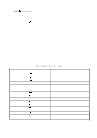
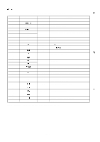
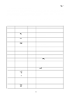
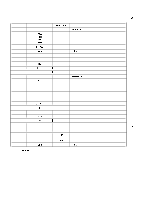
Table 2-4. Pin Function of GA E05A15HA
 |
View all Epson LQ 1050 manuals
Add to My Manuals
Save this manual to your list of manuals |
Page 73 highlights
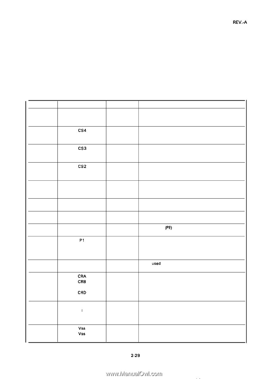
REV.-A 2.3.3.2 E05A15HA Gate Array Functions This gate array performs chip selection for the main components on the PEGX board, under the control of the 78 10HG CPU. The gate array also outputs the lower address signals (AO through A7) for the ROM and RAM using data from the CPU. In addition, the gate array controls the carriage motor and paper feed motor, and drives the printhead and plunger solenoids. Table 2-4 shows the pin assignments for the gate array. Refer to the Appendix for the details on the gate array. Pin No. 1 2 3 4 Table 2-4. Pin Function of GA (E05A15HA) Signal Name BANK O BANK 1 Direction OUT OUT Not used Function CS4 OUT Chip select signal for the gate array (7A): Low active signal CS3 OUT Chip select signal for the ST-RAM (6A): Low active signal 5 CS2 OUT Chip select signal for the ST-RAM (5A): Low active signal 6 Cs 1 OUT Chip select signal for the P-RAM (4A): Low active signal 7 P4 Not used 8 P3 IN Home Position (HP) signal input 9 P2 IN Paper End (PE) signal input 10 P1 IN Friction/Tractor switch status input Friction mode: High Tractor mode: Low 11 Po IN Not used 12 CRA OUT Carriage motor driving signal 13 CRB OUT 14 CRC OUT 15 CRD OUT 16 HD 1 OUT Printed driving signal I I (Head Data 1-8) 23 HD8 OUT 24 Vss - Logic Ground 25 Vss
-
 1
1 -
2
-
3
-
4
-
5
-
6
-
7
-
8
-
9
-
10
-
11
-
12
-
13
-
14
-
15
-
16
-
17
-
18
-
19
-
20
-
21
-
22
-
23
-
24
-
25
-
26
-
27
-
28
-
29
-
30
-
31
-
32
-
33
-
34
-
35
-
36
-
37
-
38
-
39
-
40
-
41
-
42
-
43
-
44
-
45
-
46
-
47
-
48
-
49
-
50
-
51
-
52
-
53
-
54
-
55
-
56
-
57
-
58
-
59
-
60
-
61
-
62
-
63
-
64
-
65
-
66
-
67
-
 68
68 -
 69
69 -
 70
70 -
 71
71 -
 72
72 -
 73
73 -
 74
74 -
 75
75 -
 76
76 -
 77
77 -
 78
78 -
79
-
80
-
81
-
82
-
83
-
84
-
85
-
86
-
87
-
88
-
89
-
90
-
91
-
92
-
93
-
94
-
95
-
96
-
97
-
98
-
99
-
100
-
101
-
102
-
103
-
104
-
105
-
106
-
107
-
108
-
109
-
110
-
111
-
112
-
113
-
114
-
115
-
116
-
117
-
118
-
119
-
120
-
121
-
122
-
123
-
124
-
125
-
126
-
127
-
128
-
129
-
130
-
131
-
132
-
133
-
134
-
135
-
136
-
137
-
138
-
139
-
140
-
141
-
142
-
143
-
144
-
145
-
146
-
147
-
148
-
149
-
150
-
151
-
152
-
153
-
154
-
155
-
156
-
157
-
158
-
159
-
160
-
161
-
162
-
163
-
164
-
165
-
166
-
167
-
168
-
169
-
170
-
171
-
172
-
173
-
174
-
175
-
176
-
177
-
178
-
179
-
180
-
181
-
182
-
183
-
184
-
185
-
186
-
187
-
188
-
189
-
190
-
191
-
192
-
193
-
194
-
195
-
196
-
197
-
198
-
199
-
200
-
201
-
202
-
203
-
204
-
205
-
206
-
207
-
208
-
209
-
210
-
211
-
212
-
213
-
214
-
215
-
216
-
217
-
218
-
219
-
220
-
221
-
222
-
223
-
224
-
225
 |
 |