Epson LQ 1050 Technical Manual - Page 125
Printer Mechanism's Component Relationship - driver printer
 |
View all Epson LQ 1050 manuals
Add to My Manuals
Save this manual to your list of manuals |
Page 125 highlights
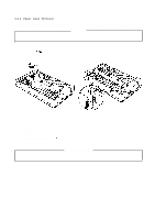
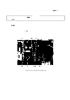
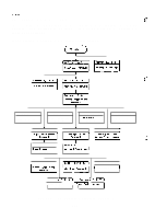
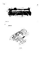
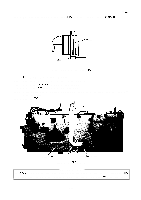
REV.-A 4.2.5 Printer Mechanism Disassembly F-"., .; This section describes the procedures for disassembling the main components of the printer mechanism. Figure 4-14 shows the relationship of the printer mechanism's major components for reference during assembly. Refer to Figures A-20 through A-25 in the Appendix during assembly. Section 4.2, 5.1 Printer mechonism Removal = I Section 4,2, 5,9 Plunger Removal I b Section 4.2,5.6 Home Position Sensor Removal I Section 4.205.3 Printheod FPC Removal A I section 402.5,8 Friction/Troctor Sensor Removal 1 n t Section 4.2, 5,7 I Section 4,2,5.4 I Section 4,2.5.5 1 =?=J -.,-. i . . . . . . Section 4.2.5.11 1 Pqwr Releose Lever Removal I Removal I I section 4,2,5.15 I I I Section 4.2, 5.16 1 I Paper Feed Roller I I Removal I 1 Section ~ I Ribbon D1river -nd sensor I I Removal II Removal I Figure 4-14. Printer Mechanism's Component Relationship 4-12
-
 1
1 -
2
-
3
-
4
-
5
-
6
-
7
-
8
-
9
-
10
-
11
-
12
-
13
-
14
-
15
-
16
-
17
-
18
-
19
-
20
-
21
-
22
-
23
-
24
-
25
-
26
-
27
-
28
-
29
-
30
-
31
-
32
-
33
-
34
-
35
-
36
-
37
-
38
-
39
-
40
-
41
-
42
-
43
-
44
-
45
-
46
-
47
-
48
-
49
-
50
-
51
-
52
-
53
-
54
-
55
-
56
-
57
-
58
-
59
-
60
-
61
-
62
-
63
-
64
-
65
-
66
-
67
-
68
-
69
-
70
-
71
-
72
-
73
-
74
-
75
-
76
-
77
-
78
-
79
-
80
-
81
-
82
-
83
-
84
-
85
-
86
-
87
-
88
-
89
-
90
-
91
-
92
-
93
-
94
-
95
-
96
-
97
-
98
-
99
-
100
-
101
-
102
-
103
-
104
-
105
-
106
-
107
-
108
-
109
-
110
-
111
-
112
-
113
-
114
-
115
-
116
-
117
-
118
-
119
-
 120
120 -
 121
121 -
 122
122 -
 123
123 -
 124
124 -
 125
125 -
 126
126 -
 127
127 -
 128
128 -
 129
129 -
 130
130 -
131
-
132
-
133
-
134
-
135
-
136
-
137
-
138
-
139
-
140
-
141
-
142
-
143
-
144
-
145
-
146
-
147
-
148
-
149
-
150
-
151
-
152
-
153
-
154
-
155
-
156
-
157
-
158
-
159
-
160
-
161
-
162
-
163
-
164
-
165
-
166
-
167
-
168
-
169
-
170
-
171
-
172
-
173
-
174
-
175
-
176
-
177
-
178
-
179
-
180
-
181
-
182
-
183
-
184
-
185
-
186
-
187
-
188
-
189
-
190
-
191
-
192
-
193
-
194
-
195
-
196
-
197
-
198
-
199
-
200
-
201
-
202
-
203
-
204
-
205
-
206
-
207
-
208
-
209
-
210
-
211
-
212
-
213
-
214
-
215
-
216
-
217
-
218
-
219
-
220
-
221
-
222
-
223
-
224
-
225
 |
 |
