Epson LQ 1050 Technical Manual - Page 97
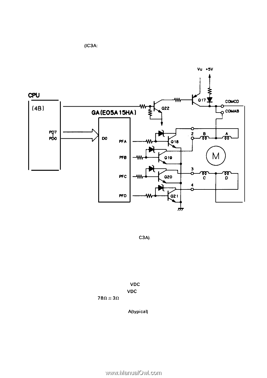
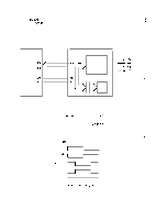
Paper Feed Motor Drive Circuit Block Diagram
 |
View all Epson LQ 1050 manuals
Add to My Manuals
Save this manual to your list of manuals |
Page 97 highlights
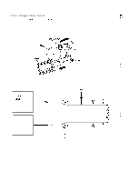
REV.-A 2.3.5.3 Paper Feed Control Circuit The paper feed mechanism of this printer is driven by the paper feed motor. The paper feed motor is controlled by a gate array (IC3A: E05A1 5HA) and the CPU. Figure 2-43 shows the paper feed motor drive circuit block diagram. vu +5V A (4B) ' c ' ?' GA(E05A ISHA) (3A) ?7 Do WA ffB -i Pfc ffD COMCD COMAB 1 r Figure 2-43. Paper Feed Motor Drive Circuit Block Diagram As you can see in Figure 2-43, the paper feed motor drive voltage is controlled by PC7 from the CPU, and phase switching is performed by the gate array (I C3A). The paper feed motor rotates in both forward and reverse directions. Since the paper feed motor rotates in the reverse direction only for micro adjustment or sheet load/eject, the paper feed motor cannot be rotated in the reverse direction by any control codes. q Paper Feed Motor Specifications Type 4-phase 48-pole PM type stepper motor Voltage Driving: + 3 6 VDC Holding: +5 VDC Coil Resistance 78Q & 3fl at 25" per phase Current Driving: 1.2 A (max.) Holding: 0.08 A(typical) Excitation 2-2 phase Paper Feed Pitch 0.118 mm/pulse (4.23 mm: 1/6": 36 pulse) 2-53
-
 1
1 -
2
-
3
-
4
-
5
-
6
-
7
-
8
-
9
-
10
-
11
-
12
-
13
-
14
-
15
-
16
-
17
-
18
-
19
-
20
-
21
-
22
-
23
-
24
-
25
-
26
-
27
-
28
-
29
-
30
-
31
-
32
-
33
-
34
-
35
-
36
-
37
-
38
-
39
-
40
-
41
-
42
-
43
-
44
-
45
-
46
-
47
-
48
-
49
-
50
-
51
-
52
-
53
-
54
-
55
-
56
-
57
-
58
-
59
-
60
-
61
-
62
-
63
-
64
-
65
-
66
-
67
-
68
-
69
-
70
-
71
-
72
-
73
-
74
-
75
-
76
-
77
-
78
-
79
-
80
-
81
-
82
-
83
-
84
-
85
-
86
-
87
-
88
-
89
-
90
-
91
-
 92
92 -
 93
93 -
 94
94 -
 95
95 -
 96
96 -
 97
97 -
 98
98 -
 99
99 -
 100
100 -
 101
101 -
 102
102 -
103
-
104
-
105
-
106
-
107
-
108
-
109
-
110
-
111
-
112
-
113
-
114
-
115
-
116
-
117
-
118
-
119
-
120
-
121
-
122
-
123
-
124
-
125
-
126
-
127
-
128
-
129
-
130
-
131
-
132
-
133
-
134
-
135
-
136
-
137
-
138
-
139
-
140
-
141
-
142
-
143
-
144
-
145
-
146
-
147
-
148
-
149
-
150
-
151
-
152
-
153
-
154
-
155
-
156
-
157
-
158
-
159
-
160
-
161
-
162
-
163
-
164
-
165
-
166
-
167
-
168
-
169
-
170
-
171
-
172
-
173
-
174
-
175
-
176
-
177
-
178
-
179
-
180
-
181
-
182
-
183
-
184
-
185
-
186
-
187
-
188
-
189
-
190
-
191
-
192
-
193
-
194
-
195
-
196
-
197
-
198
-
199
-
200
-
201
-
202
-
203
-
204
-
205
-
206
-
207
-
208
-
209
-
210
-
211
-
212
-
213
-
214
-
215
-
216
-
217
-
218
-
219
-
220
-
221
-
222
-
223
-
224
-
225
 |
 |