Epson LQ 1050 Technical Manual - Page 24
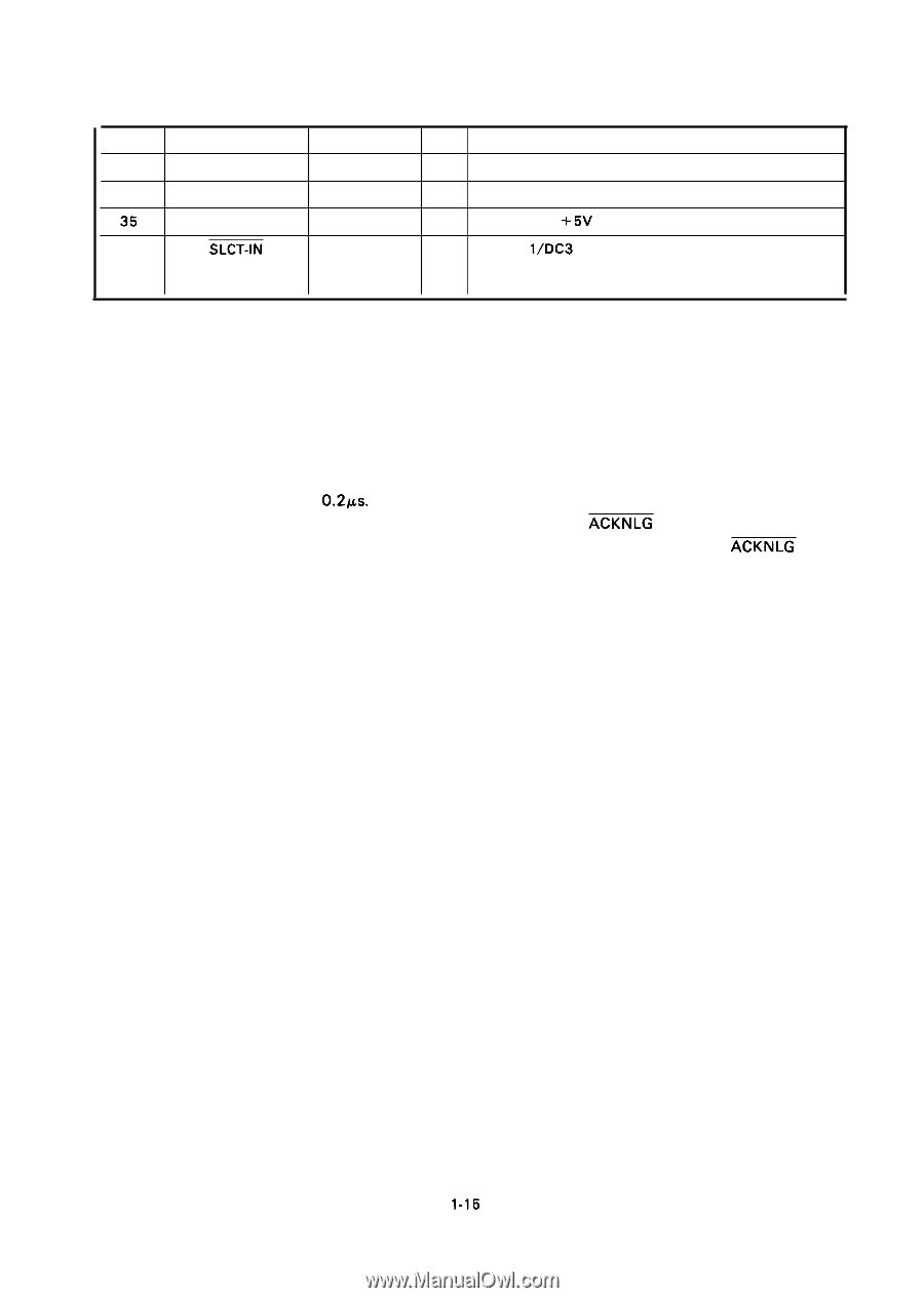
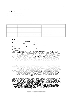
Table 1-17. Connector Pin Assignments and Signal Function cent'd
 |
View all Epson LQ 1050 manuals
Add to My Manuals
Save this manual to your list of manuals |
Page 24 highlights
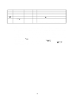
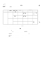
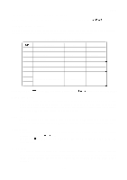
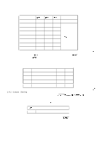
Pin No. 33 34 35 36 Table 1-17. Connector Pin Assignments and Signal Function (cent'd) REV.-A Signal Name GND NC SLCT-IN Return Pin No. DIR Functional Description Same as with Pin No. 19 to 30. Not used. Pulled up to +5V through 3.3 K ohms resistor. In The DC l/DC3 code is only valid when this signal is "HIGH" level. (Internal fixing can be carried out with Jumper- l.) NOTES: 1. "DIR" refers to the direction of signal flow as viewed from the printer. 2. "Return" denotes "TWISTED-PAIR RETURN" and is to be connected at signal ground level. As to the wiring for the interface, be sure to use a twisted-pair cable for each signal and never fail to complete connection on the Return side. To prevent noise effectively, these cables should be shielded an connected to the chassis of the host computer and the printer, respectively. 3. All interface conditions are based on TTL level. Both the rise and fall times of each signal must be less than 0.2Ks. 4. Data transfer must not be carried out by ignoring the ACKNLG or BUSY signal. (Data transfer to this printer can be carried out only after confirming the ACKNLG signal or when the level of the BUSY signal is "LOW".) 1-15
-
 1
1 -
2
-
3
-
4
-
5
-
6
-
7
-
8
-
9
-
10
-
11
-
12
-
13
-
14
-
15
-
16
-
17
-
18
-
 19
19 -
 20
20 -
 21
21 -
 22
22 -
 23
23 -
 24
24 -
 25
25 -
 26
26 -
 27
27 -
 28
28 -
 29
29 -
30
-
31
-
32
-
33
-
34
-
35
-
36
-
37
-
38
-
39
-
40
-
41
-
42
-
43
-
44
-
45
-
46
-
47
-
48
-
49
-
50
-
51
-
52
-
53
-
54
-
55
-
56
-
57
-
58
-
59
-
60
-
61
-
62
-
63
-
64
-
65
-
66
-
67
-
68
-
69
-
70
-
71
-
72
-
73
-
74
-
75
-
76
-
77
-
78
-
79
-
80
-
81
-
82
-
83
-
84
-
85
-
86
-
87
-
88
-
89
-
90
-
91
-
92
-
93
-
94
-
95
-
96
-
97
-
98
-
99
-
100
-
101
-
102
-
103
-
104
-
105
-
106
-
107
-
108
-
109
-
110
-
111
-
112
-
113
-
114
-
115
-
116
-
117
-
118
-
119
-
120
-
121
-
122
-
123
-
124
-
125
-
126
-
127
-
128
-
129
-
130
-
131
-
132
-
133
-
134
-
135
-
136
-
137
-
138
-
139
-
140
-
141
-
142
-
143
-
144
-
145
-
146
-
147
-
148
-
149
-
150
-
151
-
152
-
153
-
154
-
155
-
156
-
157
-
158
-
159
-
160
-
161
-
162
-
163
-
164
-
165
-
166
-
167
-
168
-
169
-
170
-
171
-
172
-
173
-
174
-
175
-
176
-
177
-
178
-
179
-
180
-
181
-
182
-
183
-
184
-
185
-
186
-
187
-
188
-
189
-
190
-
191
-
192
-
193
-
194
-
195
-
196
-
197
-
198
-
199
-
200
-
201
-
202
-
203
-
204
-
205
-
206
-
207
-
208
-
209
-
210
-
211
-
212
-
213
-
214
-
215
-
216
-
217
-
218
-
219
-
220
-
221
-
222
-
223
-
224
-
225
 |
 |