Epson LQ 1050 Technical Manual - Page 176
Lnn_ll
 |
View all Epson LQ 1050 manuals
Add to My Manuals
Save this manual to your list of manuals |
Page 176 highlights
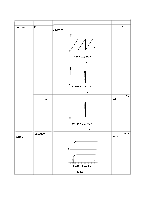
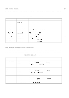
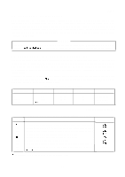
Symptom The +24V dead. Table 5-6. Power Supply Circuit Unit Repair (cent'd) Cause IC 1A is defective. Check Point Observe the oscillation waveform and the switching uvaveform. T k!k!lzk o IV/DIV, 20/.Ls/DlV Oscillation Waveform (Pin 2 of IC 1A) REV.-A Solution Replace IC 1A IOV/DIV, 20@DlV Transistors Q1O and Q1 1 are defective. Switching Waveform (Pin 1.1 of IC 1A) Observe the chopping wave form Lnn_ll o Replace Q1O or al 1 IOV/DIV, 20/.Ls/DlV Chopping Waveform (Emitter of Q1 O) Vx voltage is not Q23, Q30, and Observe the Vx voltage, when printer power is turned on. Replace Q23, Outt)ut. ZD 10 defective. Q30 or ZD1 O. v If Emitter h- Collector t ,1 2V/DIV, 5@DlV Vx Voltage Waveform (Q23) 5-19
-
 1
1 -
2
-
3
-
4
-
5
-
6
-
7
-
8
-
9
-
10
-
11
-
12
-
13
-
14
-
15
-
16
-
17
-
18
-
19
-
20
-
21
-
22
-
23
-
24
-
25
-
26
-
27
-
28
-
29
-
30
-
31
-
32
-
33
-
34
-
35
-
36
-
37
-
38
-
39
-
40
-
41
-
42
-
43
-
44
-
45
-
46
-
47
-
48
-
49
-
50
-
51
-
52
-
53
-
54
-
55
-
56
-
57
-
58
-
59
-
60
-
61
-
62
-
63
-
64
-
65
-
66
-
67
-
68
-
69
-
70
-
71
-
72
-
73
-
74
-
75
-
76
-
77
-
78
-
79
-
80
-
81
-
82
-
83
-
84
-
85
-
86
-
87
-
88
-
89
-
90
-
91
-
92
-
93
-
94
-
95
-
96
-
97
-
98
-
99
-
100
-
101
-
102
-
103
-
104
-
105
-
106
-
107
-
108
-
109
-
110
-
111
-
112
-
113
-
114
-
115
-
116
-
117
-
118
-
119
-
120
-
121
-
122
-
123
-
124
-
125
-
126
-
127
-
128
-
129
-
130
-
131
-
132
-
133
-
134
-
135
-
136
-
137
-
138
-
139
-
140
-
141
-
142
-
143
-
144
-
145
-
146
-
147
-
148
-
149
-
150
-
151
-
152
-
153
-
154
-
155
-
156
-
157
-
158
-
159
-
160
-
161
-
162
-
163
-
164
-
165
-
166
-
167
-
168
-
169
-
170
-
 171
171 -
 172
172 -
 173
173 -
 174
174 -
 175
175 -
 176
176 -
 177
177 -
 178
178 -
 179
179 -
 180
180 -
 181
181 -
182
-
183
-
184
-
185
-
186
-
187
-
188
-
189
-
190
-
191
-
192
-
193
-
194
-
195
-
196
-
197
-
198
-
199
-
200
-
201
-
202
-
203
-
204
-
205
-
206
-
207
-
208
-
209
-
210
-
211
-
212
-
213
-
214
-
215
-
216
-
217
-
218
-
219
-
220
-
221
-
222
-
223
-
224
-
225
 |
 |

REV.-A
Symptom
The
+24V
dead.
Vx voltage is not
Outt)ut.
Table 5-6. Power Supply Circuit Unit Repair (cent’d)
Cause
IC
1A is
defective.
Transistors
Q1O
and
Q1
1
are defective.
Q23,
Q30,
and
ZD 10 defective.
Check Point
Observe the oscillation waveform and the switching
uvaveform.
T
o
k!k!lzk
IV/DIV,
20/.Ls/DlV
Oscillation Waveform (Pin 2 of
IC
1A)
IOV/DIV,
20@DlV
Switching Waveform (Pin 1.1 of
IC
1A)
Observe the chopping wave form
o
Lnn_ll
IOV/DIV,
20/.Ls/DlV
Chopping Waveform (Emitter of
Q1
O)
Observe the Vx voltage, when printer power is turned on.
If
Emitter
v,
, , , , , ,
h-
Collector
t
,1, , , , , , :
2V/DIV,
5@DlV
Vx Voltage Waveform
(Q23)
Solution
Replace
IC
1A
Replace
Q1O
or
al
1
Replace
Q23,
Q30
or ZD1 O.
5-19