Epson LQ 1050 Technical Manual - Page 211
Reference voltage for CR motor phases
 |
View all Epson LQ 1050 manuals
Add to My Manuals
Save this manual to your list of manuals |
Page 211 highlights
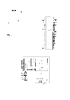
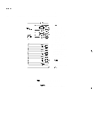
Pin No. 1 2 3 4 5 6 7 8 9 10 11 12 13 14 15 16 17 18 Signal Vcc 1 CAB S.out OA 1A IB OB Vref VCC2 Vss N.C Oc Ic ID OD C CD P.D. Rush Table A-14. STK6722H Terminal Function Direction Function In +35V DC power out CR motor phases A and B common out Surge voltage of CR motor coils out CR motor phase A drive In CR motor phase A drive pulse In CR motor phase B drive pulse out CR motor phase B drive In Reference voltage for CR motor phases In + 5V DC (internal circuit power) - GND - Not connected out CR motor phase C drive In CR motor phase C drive pulse In CR motor phase D drive pulse out CR motor phase D drive out CR motor phases C and D common In Power down - Fixed to low REV.-A
-
 1
1 -
2
-
3
-
4
-
5
-
6
-
7
-
8
-
9
-
10
-
11
-
12
-
13
-
14
-
15
-
16
-
17
-
18
-
19
-
20
-
21
-
22
-
23
-
24
-
25
-
26
-
27
-
28
-
29
-
30
-
31
-
32
-
33
-
34
-
35
-
36
-
37
-
38
-
39
-
40
-
41
-
42
-
43
-
44
-
45
-
46
-
47
-
48
-
49
-
50
-
51
-
52
-
53
-
54
-
55
-
56
-
57
-
58
-
59
-
60
-
61
-
62
-
63
-
64
-
65
-
66
-
67
-
68
-
69
-
70
-
71
-
72
-
73
-
74
-
75
-
76
-
77
-
78
-
79
-
80
-
81
-
82
-
83
-
84
-
85
-
86
-
87
-
88
-
89
-
90
-
91
-
92
-
93
-
94
-
95
-
96
-
97
-
98
-
99
-
100
-
101
-
102
-
103
-
104
-
105
-
106
-
107
-
108
-
109
-
110
-
111
-
112
-
113
-
114
-
115
-
116
-
117
-
118
-
119
-
120
-
121
-
122
-
123
-
124
-
125
-
126
-
127
-
128
-
129
-
130
-
131
-
132
-
133
-
134
-
135
-
136
-
137
-
138
-
139
-
140
-
141
-
142
-
143
-
144
-
145
-
146
-
147
-
148
-
149
-
150
-
151
-
152
-
153
-
154
-
155
-
156
-
157
-
158
-
159
-
160
-
161
-
162
-
163
-
164
-
165
-
166
-
167
-
168
-
169
-
170
-
171
-
172
-
173
-
174
-
175
-
176
-
177
-
178
-
179
-
180
-
181
-
182
-
183
-
184
-
185
-
186
-
187
-
188
-
189
-
190
-
191
-
192
-
193
-
194
-
195
-
196
-
197
-
198
-
199
-
200
-
201
-
202
-
203
-
204
-
205
-
 206
206 -
 207
207 -
 208
208 -
 209
209 -
 210
210 -
 211
211 -
 212
212 -
 213
213 -
 214
214 -
 215
215 -
 216
216 -
217
-
218
-
219
-
220
-
221
-
222
-
223
-
224
-
225
 |
 |

REV.-A
Table A-14. STK6722H Terminal Function
Pin No.
Signal
Direction
Function
1
Vcc
1
In
+35V
DC power
2
CAB
out
CR motor phases A and B common
3
S.out
out
Surge voltage of CR motor coils
4
OA
out
CR motor phase
A
drive
5
1A
In
CR motor phase A drive pulse
6
IB
In
CR motor phase B drive pulse
7
OB
out
CR motor phase B drive
8
Vref
In
Reference voltage for CR motor phases
9
VCC2
In
+ 5V DC (internal circuit power)
10
Vss
—
GND
11
N.C
—
Not connected
12
Oc
out
CR motor phase C drive
13
Ic
In
CR motor phase C drive pulse
14
ID
In
CR motor phase D drive pulse
15
OD
out
CR motor phase D drive
16
C CD
out
CR motor phases C and D common
17
P.D.
In
Power down
18
Rush
—
Fixed to low