Epson LQ 1050 Technical Manual - Page 126
Printer Mechanism Removal
 |
View all Epson LQ 1050 manuals
Add to My Manuals
Save this manual to your list of manuals |
Page 126 highlights
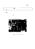
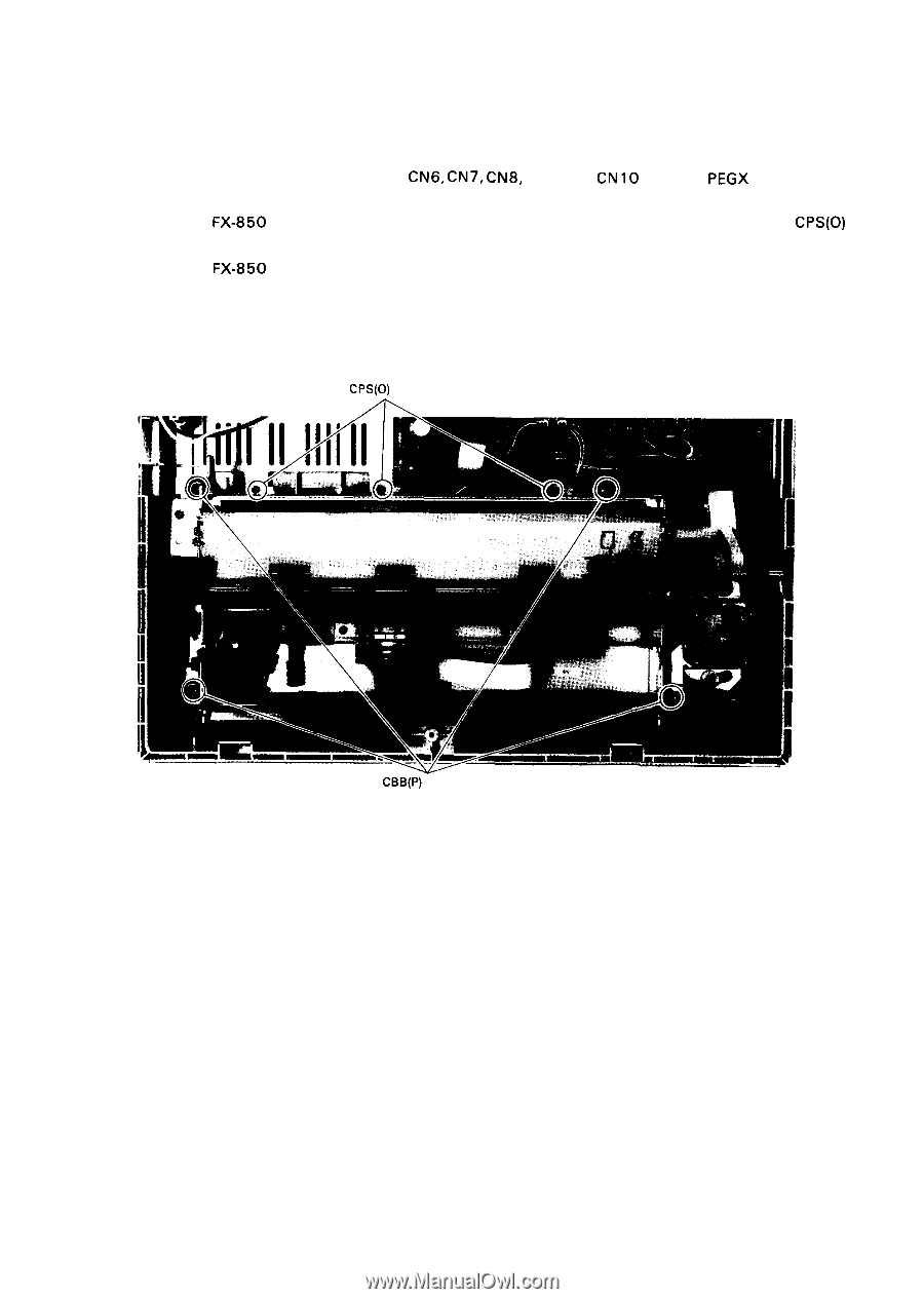
REV.-A 4.2.5.1 Printer Mechanism Removal Step 1: Remove the upper case (Refer to Section 4.2. 1.). Step 2: Remove the push tractor unit (Refer to Section 4.2.3.). Step 3: Disconnect connectors CN4, CN5, CN6, CN7, CN8, CN9, and CN 10 from the pEG)( board (Refer to Figure 4-1 O.). Step 4: For the FX-850 remove the three screws, or for the FX-1 050 remove the four screws, CPS(0) (3 X 6), which attach the ground plates to base frame. Step 5: For the FX-850 remove the four screws, or for the FX-105O remove the five screws, CBB (0) (4 X 25), securing the printer mechanism to the lower case. CPS(0) (3X 6) CBB(P) (4X 25) Figure 4-15. Printer Mechanism Removal 4-13
-
 1
1 -
2
-
3
-
4
-
5
-
6
-
7
-
8
-
9
-
10
-
11
-
12
-
13
-
14
-
15
-
16
-
17
-
18
-
19
-
20
-
21
-
22
-
23
-
24
-
25
-
26
-
27
-
28
-
29
-
30
-
31
-
32
-
33
-
34
-
35
-
36
-
37
-
38
-
39
-
40
-
41
-
42
-
43
-
44
-
45
-
46
-
47
-
48
-
49
-
50
-
51
-
52
-
53
-
54
-
55
-
56
-
57
-
58
-
59
-
60
-
61
-
62
-
63
-
64
-
65
-
66
-
67
-
68
-
69
-
70
-
71
-
72
-
73
-
74
-
75
-
76
-
77
-
78
-
79
-
80
-
81
-
82
-
83
-
84
-
85
-
86
-
87
-
88
-
89
-
90
-
91
-
92
-
93
-
94
-
95
-
96
-
97
-
98
-
99
-
100
-
101
-
102
-
103
-
104
-
105
-
106
-
107
-
108
-
109
-
110
-
111
-
112
-
113
-
114
-
115
-
116
-
117
-
118
-
119
-
120
-
 121
121 -
 122
122 -
 123
123 -
 124
124 -
 125
125 -
 126
126 -
 127
127 -
 128
128 -
 129
129 -
 130
130 -
 131
131 -
132
-
133
-
134
-
135
-
136
-
137
-
138
-
139
-
140
-
141
-
142
-
143
-
144
-
145
-
146
-
147
-
148
-
149
-
150
-
151
-
152
-
153
-
154
-
155
-
156
-
157
-
158
-
159
-
160
-
161
-
162
-
163
-
164
-
165
-
166
-
167
-
168
-
169
-
170
-
171
-
172
-
173
-
174
-
175
-
176
-
177
-
178
-
179
-
180
-
181
-
182
-
183
-
184
-
185
-
186
-
187
-
188
-
189
-
190
-
191
-
192
-
193
-
194
-
195
-
196
-
197
-
198
-
199
-
200
-
201
-
202
-
203
-
204
-
205
-
206
-
207
-
208
-
209
-
210
-
211
-
212
-
213
-
214
-
215
-
216
-
217
-
218
-
219
-
220
-
221
-
222
-
223
-
224
-
225
 |
 |
REV.-A
4.2.5.1
Step 1:
Step 2:
Step 3:
Step 4:
Step 5:
Printer Mechanism Removal
Remove the upper case (Refer to Section 4.2. 1.).
Remove the push tractor unit (Refer to Section 4.2.3.).
Disconnect connectors CN4, CN5,
CN6,
CN7,
CN8,
CN9, and
CN
10
from the
pEG)(
board (Refer
to Figure 4-1 O.).
For the
FX-850
remove the three screws, or for the FX-1 050 remove the four screws,
CPS(0)
(3 X 6), which attach the ground plates to base frame.
For the
FX-850
remove the four screws, or for the FX-105O remove the five screws, CBB (0)
(4 X 25), securing the printer mechanism to the lower case.
CPS(0)
(3X 6)
CBB(P)
(4X 25)
Figure 4-15. Printer Mechanism Removal
4-13