Epson LQ 1050 Technical Manual - Page 85
Paper Feed Control Circuit and Software Control
 |
View all Epson LQ 1050 manuals
Add to My Manuals
Save this manual to your list of manuals |
Page 85 highlights
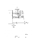
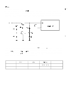
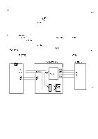
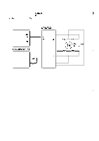
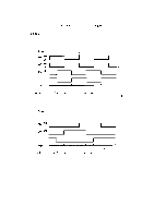
2.3.5 Printer Mechanism Control This section describes following operating principles: . Carriage Control Circuit and Software Control q Paper Feed Control Circuit and Software Control q Print Control Circuit REV.-A 2.3.5.1 Carriage Control Circuit The carriage mechanism of the printer is driven by the carriage motor. Reversing the motor rotation, holding, and phase switching for the carriage motor are controlled by the 4-phase stepper motor drive IC (IC2A: STK6722HZ). This IC (IC2A) is controlled by a gate array (IC3A: E05A15HA) which is controlled by the CPU. The rotational speed of the carriage motor is controlled by another gate array (IC3A: E05A16GA). This gate array (IC7A) also outputs the power-down signal (PD 1 ) that shuts off carriage motor drive voltage Vu when a hardware error is detected. Figure 2-33 shows the block diagram of the carriage motor control circuit. CPU P?7 ( 4 B ) PDO m m GA (E?5A 15H$) -m *m CRC CRD (3A) - m PD1 ~ m Pco PC3 (7A) GA (E05A 16GA) Figure 2-33. Carriage Motor Control Block Diagram 2-41
-
 1
1 -
2
-
3
-
4
-
5
-
6
-
7
-
8
-
9
-
10
-
11
-
12
-
13
-
14
-
15
-
16
-
17
-
18
-
19
-
20
-
21
-
22
-
23
-
24
-
25
-
26
-
27
-
28
-
29
-
30
-
31
-
32
-
33
-
34
-
35
-
36
-
37
-
38
-
39
-
40
-
41
-
42
-
43
-
44
-
45
-
46
-
47
-
48
-
49
-
50
-
51
-
52
-
53
-
54
-
55
-
56
-
57
-
58
-
59
-
60
-
61
-
62
-
63
-
64
-
65
-
66
-
67
-
68
-
69
-
70
-
71
-
72
-
73
-
74
-
75
-
76
-
77
-
78
-
79
-
 80
80 -
 81
81 -
 82
82 -
 83
83 -
 84
84 -
 85
85 -
 86
86 -
 87
87 -
 88
88 -
 89
89 -
 90
90 -
91
-
92
-
93
-
94
-
95
-
96
-
97
-
98
-
99
-
100
-
101
-
102
-
103
-
104
-
105
-
106
-
107
-
108
-
109
-
110
-
111
-
112
-
113
-
114
-
115
-
116
-
117
-
118
-
119
-
120
-
121
-
122
-
123
-
124
-
125
-
126
-
127
-
128
-
129
-
130
-
131
-
132
-
133
-
134
-
135
-
136
-
137
-
138
-
139
-
140
-
141
-
142
-
143
-
144
-
145
-
146
-
147
-
148
-
149
-
150
-
151
-
152
-
153
-
154
-
155
-
156
-
157
-
158
-
159
-
160
-
161
-
162
-
163
-
164
-
165
-
166
-
167
-
168
-
169
-
170
-
171
-
172
-
173
-
174
-
175
-
176
-
177
-
178
-
179
-
180
-
181
-
182
-
183
-
184
-
185
-
186
-
187
-
188
-
189
-
190
-
191
-
192
-
193
-
194
-
195
-
196
-
197
-
198
-
199
-
200
-
201
-
202
-
203
-
204
-
205
-
206
-
207
-
208
-
209
-
210
-
211
-
212
-
213
-
214
-
215
-
216
-
217
-
218
-
219
-
220
-
221
-
222
-
223
-
224
-
225
 |
 |
