Epson LQ 1050 Technical Manual - Page 82
ST-RAM
 |
View all Epson LQ 1050 manuals
Add to My Manuals
Save this manual to your list of manuals |
Page 82 highlights
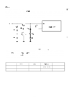
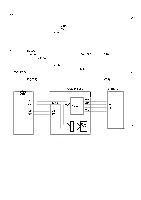
REV.-A 2.3.4.4 Memory Back-up Circuit F? The printer is equipped with SRAM (IC6A) that stores the printing mode, character pitch, and TOF (top "-- of form) position set using the control panel. The memory back-up circuit is on the PEGX board so that the settings can be maintained even when the printer power is turned off. A lithium battery is used to back up the memory. Figure 2-32 shows the memory back-up circuit. +5V * ZD8 HZS3 . ONBZ R77 150 024 A1015 R78 IK " kc :2: MS ST-RAM HM6264 (6A) R79 < ." .-, . 150 CR 17335 )77 J Figure 2-32. Memory Back-up Circuit When the power is turned on under normal conditions, +5V is applied to Vcc of the RAM and the CPU starts reading and writing. When the power is turned off, and the voltage on the + 5V line decreases to about 3.OV, transistors Q24 and Q25 are switched off and the voltage from the external lithium battery is applied to the Vcc terminal. The data in the static RAM is therefore maintained. Table 2-6 lists the static RAM conditions when the power is on or off. Table 2-6. ST-RAM Conditions Power OFF ON +5V Line L H CS2 L H Vcc [v] ST-RAM mode f": +3.0 - 3 . 3 Data holding +5 Normal 2-38 ,,
-
 1
1 -
2
-
3
-
4
-
5
-
6
-
7
-
8
-
9
-
10
-
11
-
12
-
13
-
14
-
15
-
16
-
17
-
18
-
19
-
20
-
21
-
22
-
23
-
24
-
25
-
26
-
27
-
28
-
29
-
30
-
31
-
32
-
33
-
34
-
35
-
36
-
37
-
38
-
39
-
40
-
41
-
42
-
43
-
44
-
45
-
46
-
47
-
48
-
49
-
50
-
51
-
52
-
53
-
54
-
55
-
56
-
57
-
58
-
59
-
60
-
61
-
62
-
63
-
64
-
65
-
66
-
67
-
68
-
69
-
70
-
71
-
72
-
73
-
74
-
75
-
76
-
 77
77 -
 78
78 -
 79
79 -
 80
80 -
 81
81 -
 82
82 -
 83
83 -
 84
84 -
 85
85 -
 86
86 -
 87
87 -
88
-
89
-
90
-
91
-
92
-
93
-
94
-
95
-
96
-
97
-
98
-
99
-
100
-
101
-
102
-
103
-
104
-
105
-
106
-
107
-
108
-
109
-
110
-
111
-
112
-
113
-
114
-
115
-
116
-
117
-
118
-
119
-
120
-
121
-
122
-
123
-
124
-
125
-
126
-
127
-
128
-
129
-
130
-
131
-
132
-
133
-
134
-
135
-
136
-
137
-
138
-
139
-
140
-
141
-
142
-
143
-
144
-
145
-
146
-
147
-
148
-
149
-
150
-
151
-
152
-
153
-
154
-
155
-
156
-
157
-
158
-
159
-
160
-
161
-
162
-
163
-
164
-
165
-
166
-
167
-
168
-
169
-
170
-
171
-
172
-
173
-
174
-
175
-
176
-
177
-
178
-
179
-
180
-
181
-
182
-
183
-
184
-
185
-
186
-
187
-
188
-
189
-
190
-
191
-
192
-
193
-
194
-
195
-
196
-
197
-
198
-
199
-
200
-
201
-
202
-
203
-
204
-
205
-
206
-
207
-
208
-
209
-
210
-
211
-
212
-
213
-
214
-
215
-
216
-
217
-
218
-
219
-
220
-
221
-
222
-
223
-
224
-
225
 |
 |
