Epson LQ 1050 Technical Manual - Page 80
Computef
 |
View all Epson LQ 1050 manuals
Add to My Manuals
Save this manual to your list of manuals |
Page 80 highlights
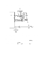
REV.-A Serial Interface Control Circuit xy.- ~ Serial data communication between the printer and host computer is controlled by the serial interface ':' board (#8 143). Other buffered serial interface boards are available. Figure 2-30 shows the serial data flow. -F+F GA d?% 8143 RXD HOST COMPUTEF BUSY/RDY DTR TXD TXD BUSY ~, I DO - t CPU (78 10HG) (4B) RXD(PC 1 ) PD7 I PDO TXD(PCO) Figure 2-30. Serial Data Flow Sequence 1. Serial data from the host computer is input to terminal IN7 of the gate array via the optional interface (8 143) using a start-stop system. The serial data is input in order of the start bit, data (7 or 8 bits), and stop bits. While a byte of data is being processed, the printer is kept in the BUSY state. 2. The data input into the gate array is serially transferred from the RXOUT terminal to the RXD terminal of the printer. 3. The byte of serial data input to the CPU is converted from serial to parallel in the CPU and stored in the input buffer. The BUSY state is cleared. 4. The printer is ready to accept the next data byte. $:-., ;" 2-36 !,
-
 1
1 -
2
-
3
-
4
-
5
-
6
-
7
-
8
-
9
-
10
-
11
-
12
-
13
-
14
-
15
-
16
-
17
-
18
-
19
-
20
-
21
-
22
-
23
-
24
-
25
-
26
-
27
-
28
-
29
-
30
-
31
-
32
-
33
-
34
-
35
-
36
-
37
-
38
-
39
-
40
-
41
-
42
-
43
-
44
-
45
-
46
-
47
-
48
-
49
-
50
-
51
-
52
-
53
-
54
-
55
-
56
-
57
-
58
-
59
-
60
-
61
-
62
-
63
-
64
-
65
-
66
-
67
-
68
-
69
-
70
-
71
-
72
-
73
-
74
-
 75
75 -
 76
76 -
 77
77 -
 78
78 -
 79
79 -
 80
80 -
 81
81 -
 82
82 -
 83
83 -
 84
84 -
 85
85 -
86
-
87
-
88
-
89
-
90
-
91
-
92
-
93
-
94
-
95
-
96
-
97
-
98
-
99
-
100
-
101
-
102
-
103
-
104
-
105
-
106
-
107
-
108
-
109
-
110
-
111
-
112
-
113
-
114
-
115
-
116
-
117
-
118
-
119
-
120
-
121
-
122
-
123
-
124
-
125
-
126
-
127
-
128
-
129
-
130
-
131
-
132
-
133
-
134
-
135
-
136
-
137
-
138
-
139
-
140
-
141
-
142
-
143
-
144
-
145
-
146
-
147
-
148
-
149
-
150
-
151
-
152
-
153
-
154
-
155
-
156
-
157
-
158
-
159
-
160
-
161
-
162
-
163
-
164
-
165
-
166
-
167
-
168
-
169
-
170
-
171
-
172
-
173
-
174
-
175
-
176
-
177
-
178
-
179
-
180
-
181
-
182
-
183
-
184
-
185
-
186
-
187
-
188
-
189
-
190
-
191
-
192
-
193
-
194
-
195
-
196
-
197
-
198
-
199
-
200
-
201
-
202
-
203
-
204
-
205
-
206
-
207
-
208
-
209
-
210
-
211
-
212
-
213
-
214
-
215
-
216
-
217
-
218
-
219
-
220
-
221
-
222
-
223
-
224
-
225
 |
 |
