Epson LQ 1050 Technical Manual - Page 162
Auto Mode with Oscilloscope, Screen Example
 |
View all Epson LQ 1050 manuals
Add to My Manuals
Save this manual to your list of manuals |
Page 162 highlights
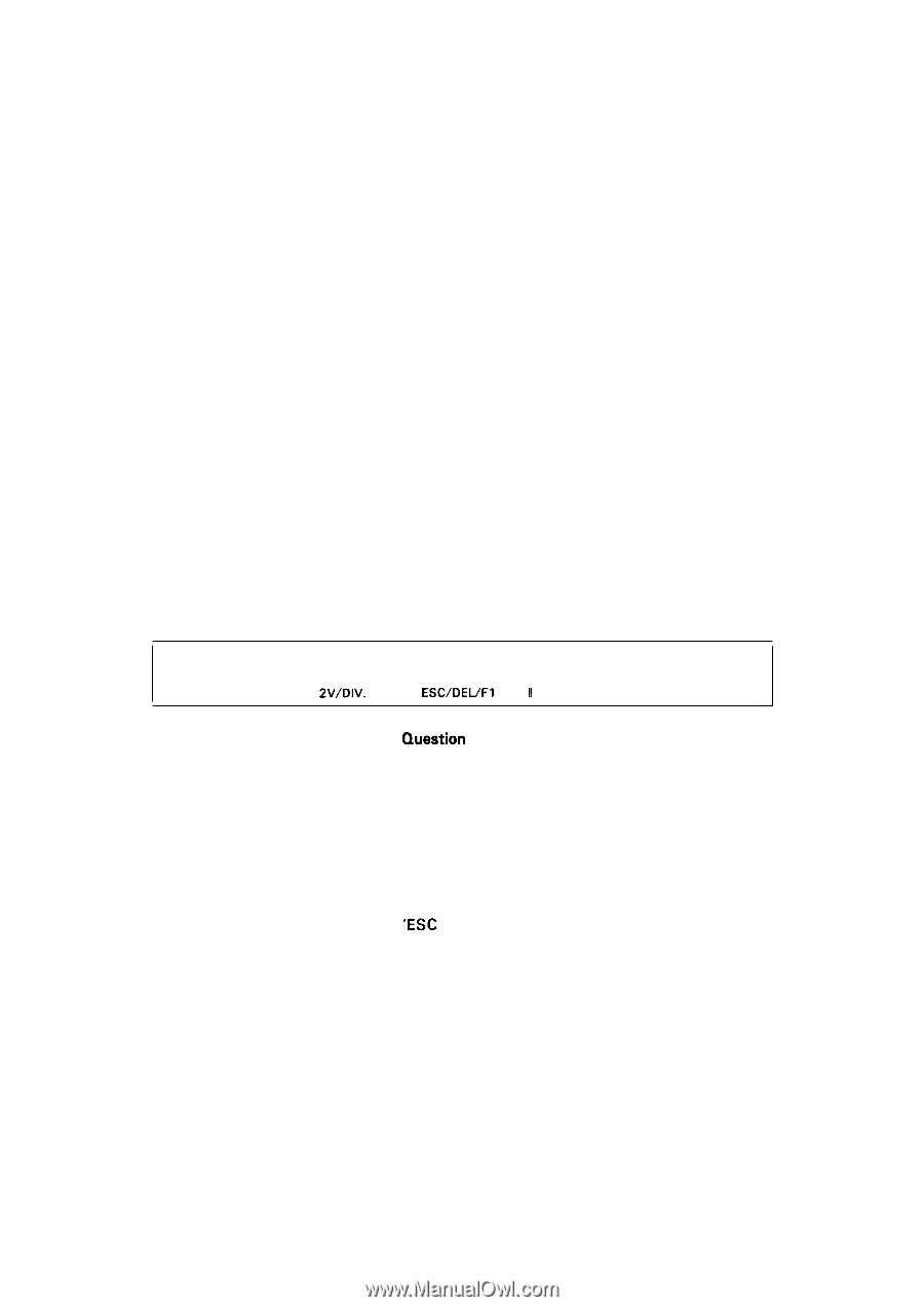
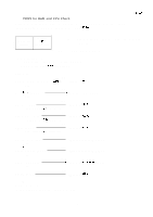
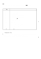
REV.-A (2) Auto File Mode This mode is selected by choosing No. 2 on the menu screen, and is used to run all of the printer checks sequentially. All of the files shown in Figures 5-5 are executed. This mode is useful in the following cases: q When the cause of the problem can not be determined. q When a final check is performed. q When a check is performed by the user without electronic or mechanical background. q After the unit has been repaired. This mode can be used to find a malfunctioning part without using specific instruments such as an oscilloscope. (3) Auto Mode with Oscilloscope This mode is selected by choosing No. 3 on the menu screen, and is used to identify malfunctions in conjunction with an oscilloscope. This mode can be used when repair is undertaken by a user who is familiar with oscilloscope operation, or when checking specific parts needing repair. The user observes waveforms and voltages on the oscilloscope by following the instructions given on the CRT screen, and inputs the results in YES/NO format. After the checks are finished, the suspected part is displayed on the screen. This mode determines the malfunctioning part at its conclusion. TO CHECK THE REFERENCE VOLTAGE OF A/D CONVERTER: IS THE VOLTAGE LEVEL OF IC7B (CPU) PIN42 ABOUT + 5V?= [NON SYNC: 2V/DIV. OR N(0) ESC/DEL/Fl KEY !1 Figure 5-6. Question Screen (Example) The 2nd line is the question. The 3rd line describes the range of oscilloscope. NON SYNC: Internal Trigger Mode SYNC: External Trigger Mode If the answer is "Yes" then press "Y". If the answer is "No" then press "N". To leave this part of the test press the 'ESC KEY' To return to a previous part of the test press the 'BS or DEL KEY'. To return to the main menu, press the 'F1 key' and 'Enter key' 5-5
-
 1
1 -
2
-
3
-
4
-
5
-
6
-
7
-
8
-
9
-
10
-
11
-
12
-
13
-
14
-
15
-
16
-
17
-
18
-
19
-
20
-
21
-
22
-
23
-
24
-
25
-
26
-
27
-
28
-
29
-
30
-
31
-
32
-
33
-
34
-
35
-
36
-
37
-
38
-
39
-
40
-
41
-
42
-
43
-
44
-
45
-
46
-
47
-
48
-
49
-
50
-
51
-
52
-
53
-
54
-
55
-
56
-
57
-
58
-
59
-
60
-
61
-
62
-
63
-
64
-
65
-
66
-
67
-
68
-
69
-
70
-
71
-
72
-
73
-
74
-
75
-
76
-
77
-
78
-
79
-
80
-
81
-
82
-
83
-
84
-
85
-
86
-
87
-
88
-
89
-
90
-
91
-
92
-
93
-
94
-
95
-
96
-
97
-
98
-
99
-
100
-
101
-
102
-
103
-
104
-
105
-
106
-
107
-
108
-
109
-
110
-
111
-
112
-
113
-
114
-
115
-
116
-
117
-
118
-
119
-
120
-
121
-
122
-
123
-
124
-
125
-
126
-
127
-
128
-
129
-
130
-
131
-
132
-
133
-
134
-
135
-
136
-
137
-
138
-
139
-
140
-
141
-
142
-
143
-
144
-
145
-
146
-
147
-
148
-
149
-
150
-
151
-
152
-
153
-
154
-
155
-
156
-
 157
157 -
 158
158 -
 159
159 -
 160
160 -
 161
161 -
 162
162 -
 163
163 -
 164
164 -
 165
165 -
 166
166 -
 167
167 -
168
-
169
-
170
-
171
-
172
-
173
-
174
-
175
-
176
-
177
-
178
-
179
-
180
-
181
-
182
-
183
-
184
-
185
-
186
-
187
-
188
-
189
-
190
-
191
-
192
-
193
-
194
-
195
-
196
-
197
-
198
-
199
-
200
-
201
-
202
-
203
-
204
-
205
-
206
-
207
-
208
-
209
-
210
-
211
-
212
-
213
-
214
-
215
-
216
-
217
-
218
-
219
-
220
-
221
-
222
-
223
-
224
-
225
 |
 |