Epson LQ 1050 Technical Manual - Page 150
Adjustment - repair
 |
View all Epson LQ 1050 manuals
Add to My Manuals
Save this manual to your list of manuals |
Page 150 highlights
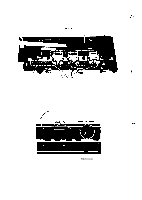
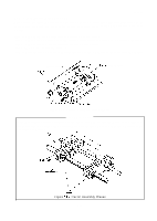
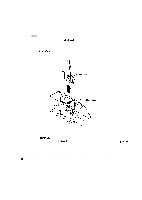
REV.-A 4.3 A D J U S T M E N T This section describes the adjustment procedures required when reassembling this printer. When disassembly or replacement is performed during maintenance or repaires of the parts described in this section, the following adjustments should be performed to ensure proper operation. 4.3.1 Platen Gap Adjustment Adjust the gap between the platen and the printhead when carriage guide shaft B is rotated or removed. Step 1: Remove the printer mechanism (Refer to Section 4.2.5. l.). Step 2: Remove the printhead (Refer to Section 4.2.5.2.). Step 3: Remove the ribbon mask. Figure 4-53. Ribbon Mask Holder and Ribbon Mask Configuration Step 4: Reinstall the printhead on the carriage. NOTE: When reinstalling the printhead, lock the head lock levers while pushing the printhead forward and downwoard. Step 5: Move the carriage to center. Step 6: Lighty loosen the HNO (4) nut securing the head adjustment lever (See Figure 4-50). Step 7: Turn the larger countersink of carriage guide shaft B upward (See Figure 4-55). Step 8: Insert the blade of a screw driver (a diameter is approx. 3 mm) into the countersink of carriage guide shaft B (See Figure 4-55). 4-37
-
 1
1 -
2
-
3
-
4
-
5
-
6
-
7
-
8
-
9
-
10
-
11
-
12
-
13
-
14
-
15
-
16
-
17
-
18
-
19
-
20
-
21
-
22
-
23
-
24
-
25
-
26
-
27
-
28
-
29
-
30
-
31
-
32
-
33
-
34
-
35
-
36
-
37
-
38
-
39
-
40
-
41
-
42
-
43
-
44
-
45
-
46
-
47
-
48
-
49
-
50
-
51
-
52
-
53
-
54
-
55
-
56
-
57
-
58
-
59
-
60
-
61
-
62
-
63
-
64
-
65
-
66
-
67
-
68
-
69
-
70
-
71
-
72
-
73
-
74
-
75
-
76
-
77
-
78
-
79
-
80
-
81
-
82
-
83
-
84
-
85
-
86
-
87
-
88
-
89
-
90
-
91
-
92
-
93
-
94
-
95
-
96
-
97
-
98
-
99
-
100
-
101
-
102
-
103
-
104
-
105
-
106
-
107
-
108
-
109
-
110
-
111
-
112
-
113
-
114
-
115
-
116
-
117
-
118
-
119
-
120
-
121
-
122
-
123
-
124
-
125
-
126
-
127
-
128
-
129
-
130
-
131
-
132
-
133
-
134
-
135
-
136
-
137
-
138
-
139
-
140
-
141
-
142
-
143
-
144
-
 145
145 -
 146
146 -
 147
147 -
 148
148 -
 149
149 -
 150
150 -
 151
151 -
 152
152 -
 153
153 -
 154
154 -
 155
155 -
156
-
157
-
158
-
159
-
160
-
161
-
162
-
163
-
164
-
165
-
166
-
167
-
168
-
169
-
170
-
171
-
172
-
173
-
174
-
175
-
176
-
177
-
178
-
179
-
180
-
181
-
182
-
183
-
184
-
185
-
186
-
187
-
188
-
189
-
190
-
191
-
192
-
193
-
194
-
195
-
196
-
197
-
198
-
199
-
200
-
201
-
202
-
203
-
204
-
205
-
206
-
207
-
208
-
209
-
210
-
211
-
212
-
213
-
214
-
215
-
216
-
217
-
218
-
219
-
220
-
221
-
222
-
223
-
224
-
225
 |
 |
