Epson LQ 1050 Technical Manual - Page 98
NI NI NI - driver +
 |
View all Epson LQ 1050 manuals
Add to My Manuals
Save this manual to your list of manuals |
Page 98 highlights
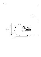
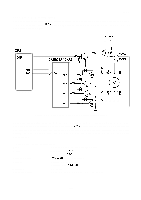
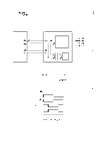
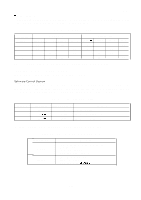
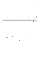
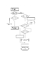
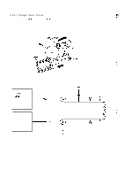
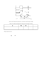
REV.-A q Gate Array (IC3A: E05A15HA) @ This gate array (IC3A) directly controls phase switching for the paper feed motor to switch the rotational direction, under control of the CPU. Data for phase switching is sent from the CPU, expanded in the paper feed motor phase switching circuit, and output as the phase switching signal to switch the rotational direction of the paper feed motor. CPU (4B) PD3 I PDO CR ~D GA[E05A15HA) 1 ( 3A) 4 Paper Feed Motor Phase Switching - Circuit G Latch ~D 1 i Mode Reg. - Figure 2-44. GA (E05A15HA) Function for Paper Feed Motor Paper Feed Motor Excitation System The paper feed motor is controlled by the open-loop constant voltage drive circuit. The phases of the paper feed motor are controlled by PFA-PFD of the gate array (IC3A: E05A15HA). 2-2 Phase excitation system is used. The paper feed motor has one driving transistor per winding (unipolar drive), two driver's become active in the 2-2 phase excitation system. Figure 2-45 shows the 2-2 phase excitation system. ,:. "-' ( IC2A) I A02 'N OFF I C02 ON OFF I I B02 'N OFF I I 002 'N OFF Step I 1 2 1 3 4 Rotation C.c. w ~ C.w Figure 2-45. Phase Excitation System 2-54
-
 1
1 -
2
-
3
-
4
-
5
-
6
-
7
-
8
-
9
-
10
-
11
-
12
-
13
-
14
-
15
-
16
-
17
-
18
-
19
-
20
-
21
-
22
-
23
-
24
-
25
-
26
-
27
-
28
-
29
-
30
-
31
-
32
-
33
-
34
-
35
-
36
-
37
-
38
-
39
-
40
-
41
-
42
-
43
-
44
-
45
-
46
-
47
-
48
-
49
-
50
-
51
-
52
-
53
-
54
-
55
-
56
-
57
-
58
-
59
-
60
-
61
-
62
-
63
-
64
-
65
-
66
-
67
-
68
-
69
-
70
-
71
-
72
-
73
-
74
-
75
-
76
-
77
-
78
-
79
-
80
-
81
-
82
-
83
-
84
-
85
-
86
-
87
-
88
-
89
-
90
-
91
-
92
-
 93
93 -
 94
94 -
 95
95 -
 96
96 -
 97
97 -
 98
98 -
 99
99 -
 100
100 -
 101
101 -
 102
102 -
 103
103 -
104
-
105
-
106
-
107
-
108
-
109
-
110
-
111
-
112
-
113
-
114
-
115
-
116
-
117
-
118
-
119
-
120
-
121
-
122
-
123
-
124
-
125
-
126
-
127
-
128
-
129
-
130
-
131
-
132
-
133
-
134
-
135
-
136
-
137
-
138
-
139
-
140
-
141
-
142
-
143
-
144
-
145
-
146
-
147
-
148
-
149
-
150
-
151
-
152
-
153
-
154
-
155
-
156
-
157
-
158
-
159
-
160
-
161
-
162
-
163
-
164
-
165
-
166
-
167
-
168
-
169
-
170
-
171
-
172
-
173
-
174
-
175
-
176
-
177
-
178
-
179
-
180
-
181
-
182
-
183
-
184
-
185
-
186
-
187
-
188
-
189
-
190
-
191
-
192
-
193
-
194
-
195
-
196
-
197
-
198
-
199
-
200
-
201
-
202
-
203
-
204
-
205
-
206
-
207
-
208
-
209
-
210
-
211
-
212
-
213
-
214
-
215
-
216
-
217
-
218
-
219
-
220
-
221
-
222
-
223
-
224
-
225
 |
 |
