Epson LQ 1050 Technical Manual - Page 45
General
 |
View all Epson LQ 1050 manuals
Add to My Manuals
Save this manual to your list of manuals |
Page 45 highlights
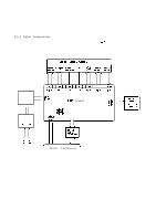
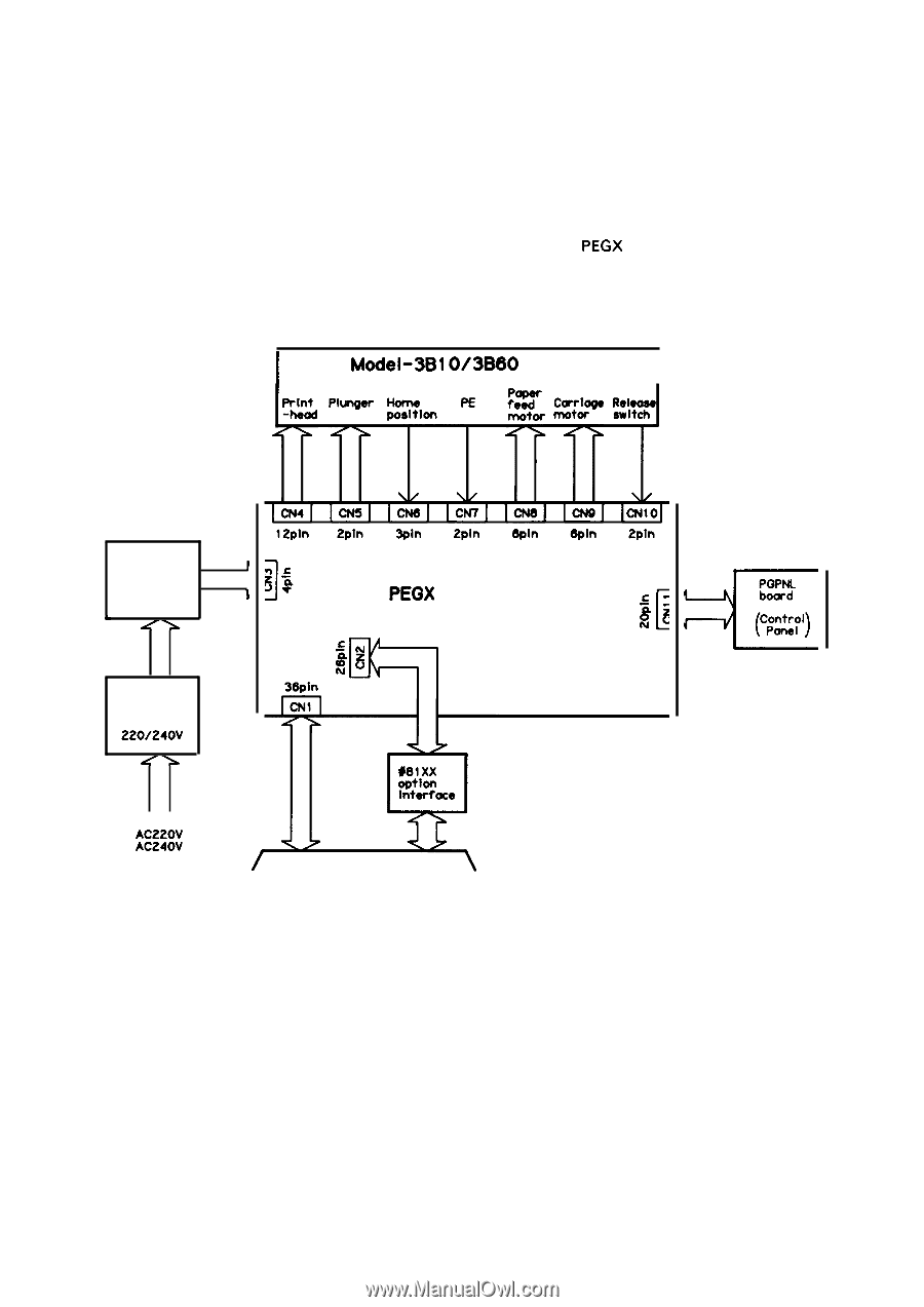
REV.-A 2.1 GENERAL This chapter describes the operation of each component. Section 2.2 and the subsequent sections give more detailed descriptions of each component. 2.1.1 Cable Connections The printer components are connected to and controlled by the PEGX board. Figure 2-1 shows the interconnection of the components. I Model-3Bl O/3B60 I Power Transformer f 120V 220V & 240V /> 1 PEGX board PEGFLU board 120V 220/240V LL AC120V AC220V AC240V / Host computer ' Figure 2-1. Cable Connections PGPNL board (c%%') < 2-1
-
 1
1 -
2
-
3
-
4
-
5
-
6
-
7
-
8
-
9
-
10
-
11
-
12
-
13
-
14
-
15
-
16
-
17
-
18
-
19
-
20
-
21
-
22
-
23
-
24
-
25
-
26
-
27
-
28
-
29
-
30
-
31
-
32
-
33
-
34
-
35
-
36
-
37
-
38
-
39
-
 40
40 -
 41
41 -
 42
42 -
 43
43 -
 44
44 -
 45
45 -
 46
46 -
 47
47 -
 48
48 -
 49
49 -
 50
50 -
51
-
52
-
53
-
54
-
55
-
56
-
57
-
58
-
59
-
60
-
61
-
62
-
63
-
64
-
65
-
66
-
67
-
68
-
69
-
70
-
71
-
72
-
73
-
74
-
75
-
76
-
77
-
78
-
79
-
80
-
81
-
82
-
83
-
84
-
85
-
86
-
87
-
88
-
89
-
90
-
91
-
92
-
93
-
94
-
95
-
96
-
97
-
98
-
99
-
100
-
101
-
102
-
103
-
104
-
105
-
106
-
107
-
108
-
109
-
110
-
111
-
112
-
113
-
114
-
115
-
116
-
117
-
118
-
119
-
120
-
121
-
122
-
123
-
124
-
125
-
126
-
127
-
128
-
129
-
130
-
131
-
132
-
133
-
134
-
135
-
136
-
137
-
138
-
139
-
140
-
141
-
142
-
143
-
144
-
145
-
146
-
147
-
148
-
149
-
150
-
151
-
152
-
153
-
154
-
155
-
156
-
157
-
158
-
159
-
160
-
161
-
162
-
163
-
164
-
165
-
166
-
167
-
168
-
169
-
170
-
171
-
172
-
173
-
174
-
175
-
176
-
177
-
178
-
179
-
180
-
181
-
182
-
183
-
184
-
185
-
186
-
187
-
188
-
189
-
190
-
191
-
192
-
193
-
194
-
195
-
196
-
197
-
198
-
199
-
200
-
201
-
202
-
203
-
204
-
205
-
206
-
207
-
208
-
209
-
210
-
211
-
212
-
213
-
214
-
215
-
216
-
217
-
218
-
219
-
220
-
221
-
222
-
223
-
224
-
225
 |
 |
REV.-A
2.1 GENERAL
This chapter describes the operation of each component. Section 2.2 and the subsequent sections give
more detailed descriptions of each component.
2.1.1 Cable Connections
The printer components are connected to and controlled by the
PEGX
board. Figure 2-1 shows the
interconnection of the components.
Power
Transformer
f
120V
220V
1
240V
&
/>
PEGFLU
board
120V
220/240V
LL
AC120V
AC220V
AC240V
/
I
Model-3Bl
O/3B60
I
PEGX
board
Host computer
‘
<
PGPNL
board
(c%%’)
Figure 2-1. Cable Connections
2-1