Epson LQ 1050 Technical Manual - Page 86
STK6722
 |
View all Epson LQ 1050 manuals
Add to My Manuals
Save this manual to your list of manuals |
Page 86 highlights
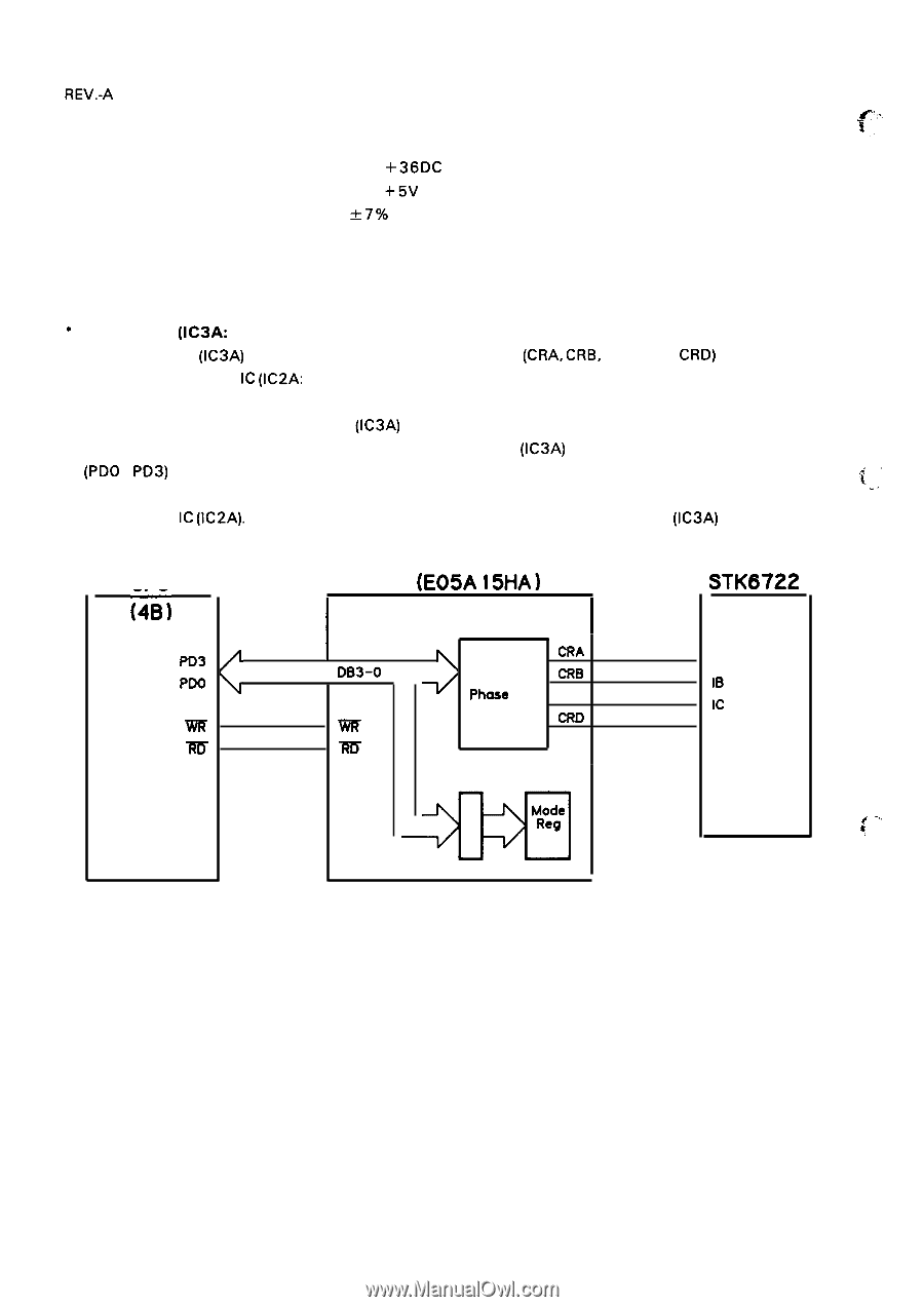
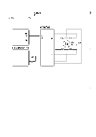
REV.-A Carriage Motor Specifications Type Voltage 4-phase 200-pole stepper motor Driving: +36DC Holding: +5V DC Coil Resistance 110 & 7Y0 at 25°C per phase Current Driving: 0.68A (max.) Hoding: O. 15A (typical) Excitation 1-2 phase, 2-2 phase * Gate Array (IC3A: E05A15HA) This gate array (IC3A) outputs the phase-switching signals (CRA, CRB, CRC, and CRD) to the 4-phase stepper motor drive IC (IC2A: STK6722HZ), under the control of the CPU. Phase-switching cycles and timing vary depending on the speed and the mode (forward or reverse) of the carriage. The mode register in the gate array (IC3A) determines the carriage movement direction and phase switching method, and is fed by the CPU. The gate array (IC3A) expands the phase data (PDO - PD3) from the CPU in the carriage motor phase-switching circuit in accordance with the "c.-, direction and method determined by the mode register, and outputs the data to the 4-phase stepper motor drive IC (IC2A). Figure 2-34 shows the block diagram of the gate array (IC3A) operation. CPU i4B-) PD3 4 PDO Rf5 GA (E05A 15HA) 4 I (3A) I I DB3-O Carriage CI?A Motor CRB Phose CRC ViR Switching CRD Circuit -m Latch - m STK6722 (2A) 1A IB Ic ID f"" .. .. . Figure 2-34. GA (E05A15HA) Operation Diagram 2-42
-
 1
1 -
2
-
3
-
4
-
5
-
6
-
7
-
8
-
9
-
10
-
11
-
12
-
13
-
14
-
15
-
16
-
17
-
18
-
19
-
20
-
21
-
22
-
23
-
24
-
25
-
26
-
27
-
28
-
29
-
30
-
31
-
32
-
33
-
34
-
35
-
36
-
37
-
38
-
39
-
40
-
41
-
42
-
43
-
44
-
45
-
46
-
47
-
48
-
49
-
50
-
51
-
52
-
53
-
54
-
55
-
56
-
57
-
58
-
59
-
60
-
61
-
62
-
63
-
64
-
65
-
66
-
67
-
68
-
69
-
70
-
71
-
72
-
73
-
74
-
75
-
76
-
77
-
78
-
79
-
80
-
 81
81 -
 82
82 -
 83
83 -
 84
84 -
 85
85 -
 86
86 -
 87
87 -
 88
88 -
 89
89 -
 90
90 -
 91
91 -
92
-
93
-
94
-
95
-
96
-
97
-
98
-
99
-
100
-
101
-
102
-
103
-
104
-
105
-
106
-
107
-
108
-
109
-
110
-
111
-
112
-
113
-
114
-
115
-
116
-
117
-
118
-
119
-
120
-
121
-
122
-
123
-
124
-
125
-
126
-
127
-
128
-
129
-
130
-
131
-
132
-
133
-
134
-
135
-
136
-
137
-
138
-
139
-
140
-
141
-
142
-
143
-
144
-
145
-
146
-
147
-
148
-
149
-
150
-
151
-
152
-
153
-
154
-
155
-
156
-
157
-
158
-
159
-
160
-
161
-
162
-
163
-
164
-
165
-
166
-
167
-
168
-
169
-
170
-
171
-
172
-
173
-
174
-
175
-
176
-
177
-
178
-
179
-
180
-
181
-
182
-
183
-
184
-
185
-
186
-
187
-
188
-
189
-
190
-
191
-
192
-
193
-
194
-
195
-
196
-
197
-
198
-
199
-
200
-
201
-
202
-
203
-
204
-
205
-
206
-
207
-
208
-
209
-
210
-
211
-
212
-
213
-
214
-
215
-
216
-
217
-
218
-
219
-
220
-
221
-
222
-
223
-
224
-
225
 |
 |