Epson LQ 1050 Technical Manual - Page 46
Table 2-1 Board Connector Summary
 |
View all Epson LQ 1050 manuals
Add to My Manuals
Save this manual to your list of manuals |
Page 46 highlights
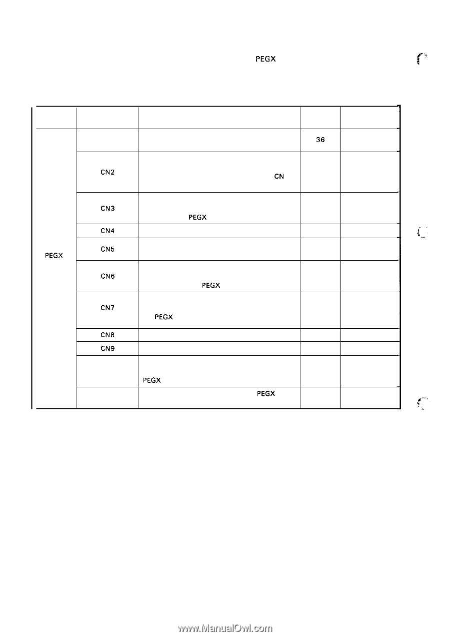
REV.-A ":, Each component is connected to one of the connectors on the PEGX board, which are listed in Table c 2-1. Table 2-1 describes the connectors. Table 2-1 Board Connector Summary Circuit Board Connector Number Description Number of Pins Reference Table CN 1 Standard 8-bit parallel interface connector. 36 Used for data transfer from the host computer. Table A-1 5 Connector for the optional interface board. Used CN2 for data transfer from the host computer. When 26 the optional interface board is mounted, CN 1 is Table A-1 6 invalid. Supplies two step-down AC voltages from the CN3 power supply transformer to the DC regulator 4 Table A-1 7 circuit on the PEGX board. PEGX board CN4 Drives the printhead needles. 12 Table A-1 8 '(,.' CN5 Drives the plunger that opens and shuts the 2 paper bail on the printer mechanism. Table A-1 9 Transfers the state of the carriage home position CN6 sensor from the printer mechanism to the con- 3 Table A-20 trol circuit on the PEGX board. Transfers the state of the paper end sensor from CN7 the printer mechanism to the control circuit on 2 Table A-2 1 the PEGX board. CN8 CN9 CN 10 CN 11 Drives the paper feed motor. 6 Drives the carriage motor. 9 Transfers the state of the release lever from the printer mechanism to the control circuit on the 2 PEGX board. Interface connector between the PEGX board 20 and the control panel. Table A-22 Table A-23 Table A-24 Table A-25 2-2
-
 1
1 -
2
-
3
-
4
-
5
-
6
-
7
-
8
-
9
-
10
-
11
-
12
-
13
-
14
-
15
-
16
-
17
-
18
-
19
-
20
-
21
-
22
-
23
-
24
-
25
-
26
-
27
-
28
-
29
-
30
-
31
-
32
-
33
-
34
-
35
-
36
-
37
-
38
-
39
-
40
-
 41
41 -
 42
42 -
 43
43 -
 44
44 -
 45
45 -
 46
46 -
 47
47 -
 48
48 -
 49
49 -
 50
50 -
 51
51 -
52
-
53
-
54
-
55
-
56
-
57
-
58
-
59
-
60
-
61
-
62
-
63
-
64
-
65
-
66
-
67
-
68
-
69
-
70
-
71
-
72
-
73
-
74
-
75
-
76
-
77
-
78
-
79
-
80
-
81
-
82
-
83
-
84
-
85
-
86
-
87
-
88
-
89
-
90
-
91
-
92
-
93
-
94
-
95
-
96
-
97
-
98
-
99
-
100
-
101
-
102
-
103
-
104
-
105
-
106
-
107
-
108
-
109
-
110
-
111
-
112
-
113
-
114
-
115
-
116
-
117
-
118
-
119
-
120
-
121
-
122
-
123
-
124
-
125
-
126
-
127
-
128
-
129
-
130
-
131
-
132
-
133
-
134
-
135
-
136
-
137
-
138
-
139
-
140
-
141
-
142
-
143
-
144
-
145
-
146
-
147
-
148
-
149
-
150
-
151
-
152
-
153
-
154
-
155
-
156
-
157
-
158
-
159
-
160
-
161
-
162
-
163
-
164
-
165
-
166
-
167
-
168
-
169
-
170
-
171
-
172
-
173
-
174
-
175
-
176
-
177
-
178
-
179
-
180
-
181
-
182
-
183
-
184
-
185
-
186
-
187
-
188
-
189
-
190
-
191
-
192
-
193
-
194
-
195
-
196
-
197
-
198
-
199
-
200
-
201
-
202
-
203
-
204
-
205
-
206
-
207
-
208
-
209
-
210
-
211
-
212
-
213
-
214
-
215
-
216
-
217
-
218
-
219
-
220
-
221
-
222
-
223
-
224
-
225
 |
 |