Epson LQ 1050 Technical Manual - Page 69
CN1 O
 |
View all Epson LQ 1050 manuals
Add to My Manuals
Save this manual to your list of manuals |
Page 69 highlights
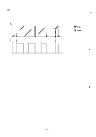
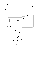
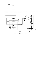
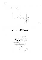
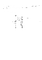
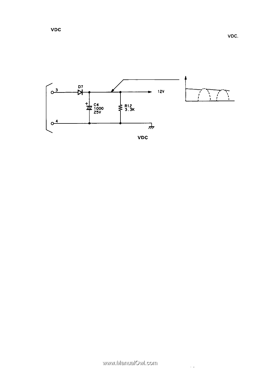
REV.-A 2.3.2.8 +12 VDC Supply Circuit The 12 VAC from the transformer is half-wave recrified by diode D7 and is converted to +12 VDC. As shown by Figure 2-25, the half-wave rectified voltages pass through the capacitor smoothing circuit so that the ripple is small, and the average DC voltage rises when no load current flows and drops as load current increases. ["zz::3 CN1 O 4 D7 + C4 1000 25V R12 3. 3K + 12V v & I1' .- \!\I) I/ -y$tI Figure 2-25. +12 VDC Circuit 2-25 ,,
-
 1
1 -
2
-
3
-
4
-
5
-
6
-
7
-
8
-
9
-
10
-
11
-
12
-
13
-
14
-
15
-
16
-
17
-
18
-
19
-
20
-
21
-
22
-
23
-
24
-
25
-
26
-
27
-
28
-
29
-
30
-
31
-
32
-
33
-
34
-
35
-
36
-
37
-
38
-
39
-
40
-
41
-
42
-
43
-
44
-
45
-
46
-
47
-
48
-
49
-
50
-
51
-
52
-
53
-
54
-
55
-
56
-
57
-
58
-
59
-
60
-
61
-
62
-
63
-
 64
64 -
 65
65 -
 66
66 -
 67
67 -
 68
68 -
 69
69 -
 70
70 -
 71
71 -
 72
72 -
 73
73 -
 74
74 -
75
-
76
-
77
-
78
-
79
-
80
-
81
-
82
-
83
-
84
-
85
-
86
-
87
-
88
-
89
-
90
-
91
-
92
-
93
-
94
-
95
-
96
-
97
-
98
-
99
-
100
-
101
-
102
-
103
-
104
-
105
-
106
-
107
-
108
-
109
-
110
-
111
-
112
-
113
-
114
-
115
-
116
-
117
-
118
-
119
-
120
-
121
-
122
-
123
-
124
-
125
-
126
-
127
-
128
-
129
-
130
-
131
-
132
-
133
-
134
-
135
-
136
-
137
-
138
-
139
-
140
-
141
-
142
-
143
-
144
-
145
-
146
-
147
-
148
-
149
-
150
-
151
-
152
-
153
-
154
-
155
-
156
-
157
-
158
-
159
-
160
-
161
-
162
-
163
-
164
-
165
-
166
-
167
-
168
-
169
-
170
-
171
-
172
-
173
-
174
-
175
-
176
-
177
-
178
-
179
-
180
-
181
-
182
-
183
-
184
-
185
-
186
-
187
-
188
-
189
-
190
-
191
-
192
-
193
-
194
-
195
-
196
-
197
-
198
-
199
-
200
-
201
-
202
-
203
-
204
-
205
-
206
-
207
-
208
-
209
-
210
-
211
-
212
-
213
-
214
-
215
-
216
-
217
-
218
-
219
-
220
-
221
-
222
-
223
-
224
-
225
 |
 |
REV.-A
2.3.2.8 +12
VDC
Supply Circuit
The 12 VAC from the transformer is half-wave recrified by diode D7 and is converted to +12
VDC.
As shown by Figure 2-25, the half-wave rectified voltages pass through the capacitor smoothing circuit
so that the ripple is small, and the average DC voltage rises when no load current flows and drops as
load current increases.
v
[“z
z::
D7
3
&
.-
+
12V
\
-y
1’
!)
$
I
\
/
t
II
I
+
C4
CN1 O
1000
R12
25V
3. 3K
4
Figure 2-25. +12
VDC
Circuit
2-25
,,