Epson LQ 1050 Technical Manual - Page 62
mitterarrentOf, omrEILO
 |
View all Epson LQ 1050 manuals
Add to My Manuals
Save this manual to your list of manuals |
Page 62 highlights
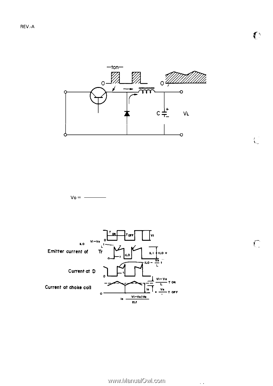
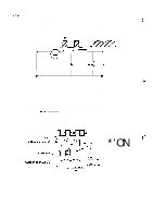
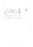
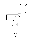
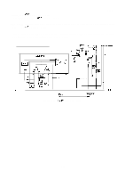
REV.-A 2.3.2.4 Chopper-Type Switching Regulator Circuit A chopper-type switching regulator is employed in the power supply circuit. Operation of the step-down circuit is as follows: -ton- .U , *Z / =ZZZ o i--~ t o Tr L f VI D c-: Vo< VL T o Figure 2-14. Step-Down Circuit Figure 2-14 shows the chopper-type, step-down switching regulator circuit. When the transistor is ON, voltage Vi is applied to coil L and capacitor C, and load current IL flows. At this time, electromagnetic energy WL is accumulated in choke coil L. When the transistor turns off, WL is applied to the load via flywheel diode D so that output voltage Vo becomes the average value: V. = Vi X Ton T where, T = Ton + Toff (T is constant) Therefore, Vo can be held constant by controlling Ton. Figure 2-15 shows the step down timings. Voltage between the collector and the emitter of Tr 'mit erarrentOf ;omrEILO+ *'ON "- Lo -V1-v-e lo- , Current at diode D when It is reverse recovered. (-' m-" cuwentdD Current"t'okecoi' oz2rEs'::F ILO = 10 - ( V1-vo)vo L 2Lt V 1 Figure 2-15. Step-Down Timings 2-18 ,.
-
 1
1 -
2
-
3
-
4
-
5
-
6
-
7
-
8
-
9
-
10
-
11
-
12
-
13
-
14
-
15
-
16
-
17
-
18
-
19
-
20
-
21
-
22
-
23
-
24
-
25
-
26
-
27
-
28
-
29
-
30
-
31
-
32
-
33
-
34
-
35
-
36
-
37
-
38
-
39
-
40
-
41
-
42
-
43
-
44
-
45
-
46
-
47
-
48
-
49
-
50
-
51
-
52
-
53
-
54
-
55
-
56
-
 57
57 -
 58
58 -
 59
59 -
 60
60 -
 61
61 -
 62
62 -
 63
63 -
 64
64 -
 65
65 -
 66
66 -
 67
67 -
68
-
69
-
70
-
71
-
72
-
73
-
74
-
75
-
76
-
77
-
78
-
79
-
80
-
81
-
82
-
83
-
84
-
85
-
86
-
87
-
88
-
89
-
90
-
91
-
92
-
93
-
94
-
95
-
96
-
97
-
98
-
99
-
100
-
101
-
102
-
103
-
104
-
105
-
106
-
107
-
108
-
109
-
110
-
111
-
112
-
113
-
114
-
115
-
116
-
117
-
118
-
119
-
120
-
121
-
122
-
123
-
124
-
125
-
126
-
127
-
128
-
129
-
130
-
131
-
132
-
133
-
134
-
135
-
136
-
137
-
138
-
139
-
140
-
141
-
142
-
143
-
144
-
145
-
146
-
147
-
148
-
149
-
150
-
151
-
152
-
153
-
154
-
155
-
156
-
157
-
158
-
159
-
160
-
161
-
162
-
163
-
164
-
165
-
166
-
167
-
168
-
169
-
170
-
171
-
172
-
173
-
174
-
175
-
176
-
177
-
178
-
179
-
180
-
181
-
182
-
183
-
184
-
185
-
186
-
187
-
188
-
189
-
190
-
191
-
192
-
193
-
194
-
195
-
196
-
197
-
198
-
199
-
200
-
201
-
202
-
203
-
204
-
205
-
206
-
207
-
208
-
209
-
210
-
211
-
212
-
213
-
214
-
215
-
216
-
217
-
218
-
219
-
220
-
221
-
222
-
223
-
224
-
225
 |
 |