Epson LQ 1050 Technical Manual - Page 77
Reset Circuit
 |
View all Epson LQ 1050 manuals
Add to My Manuals
Save this manual to your list of manuals |
Page 77 highlights
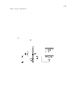
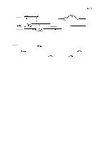
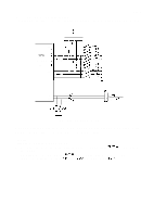
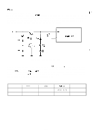
REV.-A 2.3.4 Main Circuit Operation All the printer operations are controlled by the PEGX board. The printer control can be divided into two sections: the main control for the host computer interface, printer initialization, memory control, analog signal detection, and reading the DIP switch settings, and error detection and mechanism control for driving the printer mechanisms such as the carriage motor, paper feed motor, plunger, and printhead. This section describes the operation of the following: q Reset Circuit q Interface Control Circuit q Memory Back-up Circuit q Error-Detection 2.3.4.1 Reset Circuit The printer is reset when any of the following occur: q The printer power is turned on (hardware initialization). q The initialization signal (INIT) is received from the host computer (hardware initialization). q Control code ESC @ is received from the host computer (software initialization). The reset operation performed for the ESC @ code is different from that for the other two cases. Figure 2-27 shows the reset circuit. w d.,, F R80 IK y!: + R99 IK 2. 2N 1"* +'"'"'"I' ST-RAM (6A) CS2 o I Figure 2-27. Reset Circuit Refer to Section 1.7 for information on hardware and software initialization. 2-33 ,,
-
 1
1 -
2
-
3
-
4
-
5
-
6
-
7
-
8
-
9
-
10
-
11
-
12
-
13
-
14
-
15
-
16
-
17
-
18
-
19
-
20
-
21
-
22
-
23
-
24
-
25
-
26
-
27
-
28
-
29
-
30
-
31
-
32
-
33
-
34
-
35
-
36
-
37
-
38
-
39
-
40
-
41
-
42
-
43
-
44
-
45
-
46
-
47
-
48
-
49
-
50
-
51
-
52
-
53
-
54
-
55
-
56
-
57
-
58
-
59
-
60
-
61
-
62
-
63
-
64
-
65
-
66
-
67
-
68
-
69
-
70
-
71
-
 72
72 -
 73
73 -
 74
74 -
 75
75 -
 76
76 -
 77
77 -
 78
78 -
 79
79 -
 80
80 -
 81
81 -
 82
82 -
83
-
84
-
85
-
86
-
87
-
88
-
89
-
90
-
91
-
92
-
93
-
94
-
95
-
96
-
97
-
98
-
99
-
100
-
101
-
102
-
103
-
104
-
105
-
106
-
107
-
108
-
109
-
110
-
111
-
112
-
113
-
114
-
115
-
116
-
117
-
118
-
119
-
120
-
121
-
122
-
123
-
124
-
125
-
126
-
127
-
128
-
129
-
130
-
131
-
132
-
133
-
134
-
135
-
136
-
137
-
138
-
139
-
140
-
141
-
142
-
143
-
144
-
145
-
146
-
147
-
148
-
149
-
150
-
151
-
152
-
153
-
154
-
155
-
156
-
157
-
158
-
159
-
160
-
161
-
162
-
163
-
164
-
165
-
166
-
167
-
168
-
169
-
170
-
171
-
172
-
173
-
174
-
175
-
176
-
177
-
178
-
179
-
180
-
181
-
182
-
183
-
184
-
185
-
186
-
187
-
188
-
189
-
190
-
191
-
192
-
193
-
194
-
195
-
196
-
197
-
198
-
199
-
200
-
201
-
202
-
203
-
204
-
205
-
206
-
207
-
208
-
209
-
210
-
211
-
212
-
213
-
214
-
215
-
216
-
217
-
218
-
219
-
220
-
221
-
222
-
223
-
224
-
225
 |
 |
