Epson LQ 1050 Technical Manual - Page 91
Carriage Motor Drive Circuit Block Diagram - + driver
 |
View all Epson LQ 1050 manuals
Add to My Manuals
Save this manual to your list of manuals |
Page 91 highlights
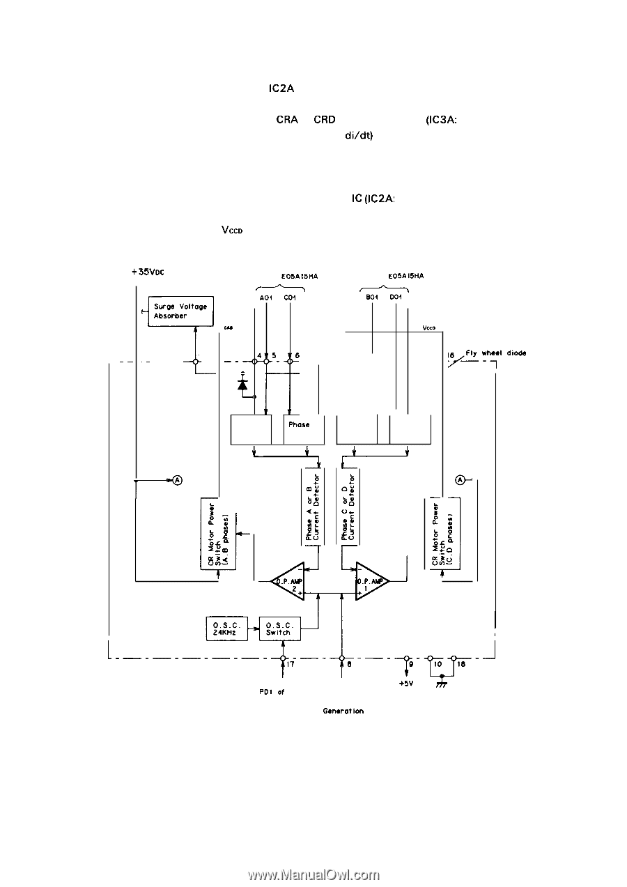
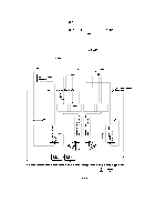
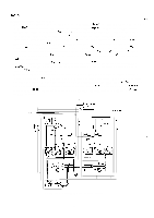
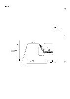
REV.-A General Operation Figure 2-38 shows the block diagram of IC2A (STK6722). The carriage motor has four coils A, B, C, and D, and each coil is driven by the corresponding phase driver A to D. These phase drivers are switched directory by the output pulses from ports CRA to CRD of the gate array (IC3A: E05A15HA). When the phase drivers are turned off, the surge voltage (e = - L X diidt) generated from the coils of the carriage motor is applied to the surge voltage absorber via the flywheel diode attached to each phase driver, and is absorbed. This circuit drives the carriage motor using a constant current chopper type drive system. Most of this circuit is included in the 4 phase stepper motor driver IC (IC2A: STK6722HA). Chopper control is performed using a separately-excited system (oscillation frequency: approximately 24 KHz). The carriage motor supply voltages VCAB and VCCD are applied intermittently so that the coil current is kept constant. +35VDC Surge Voltoge Absorber w ~ .- ,1 . - - '3 - - - 2 - + From E05A15HA A04 Col A B From E05A15HA ~ B04 Vcco ) Phase A Driver Phose B Driver Phase C Driver Phase D Driver -1 r I 1.-------%-LET', I Polof E05A16GA I Vref +5V h From Reference Voltage ( Generotlon Circuit ) Figure 2-38. Carriage Motor Drive Circuit Block Diagram 2-47
-
 1
1 -
2
-
3
-
4
-
5
-
6
-
7
-
8
-
9
-
10
-
11
-
12
-
13
-
14
-
15
-
16
-
17
-
18
-
19
-
20
-
21
-
22
-
23
-
24
-
25
-
26
-
27
-
28
-
29
-
30
-
31
-
32
-
33
-
34
-
35
-
36
-
37
-
38
-
39
-
40
-
41
-
42
-
43
-
44
-
45
-
46
-
47
-
48
-
49
-
50
-
51
-
52
-
53
-
54
-
55
-
56
-
57
-
58
-
59
-
60
-
61
-
62
-
63
-
64
-
65
-
66
-
67
-
68
-
69
-
70
-
71
-
72
-
73
-
74
-
75
-
76
-
77
-
78
-
79
-
80
-
81
-
82
-
83
-
84
-
85
-
 86
86 -
 87
87 -
 88
88 -
 89
89 -
 90
90 -
 91
91 -
 92
92 -
 93
93 -
 94
94 -
 95
95 -
 96
96 -
97
-
98
-
99
-
100
-
101
-
102
-
103
-
104
-
105
-
106
-
107
-
108
-
109
-
110
-
111
-
112
-
113
-
114
-
115
-
116
-
117
-
118
-
119
-
120
-
121
-
122
-
123
-
124
-
125
-
126
-
127
-
128
-
129
-
130
-
131
-
132
-
133
-
134
-
135
-
136
-
137
-
138
-
139
-
140
-
141
-
142
-
143
-
144
-
145
-
146
-
147
-
148
-
149
-
150
-
151
-
152
-
153
-
154
-
155
-
156
-
157
-
158
-
159
-
160
-
161
-
162
-
163
-
164
-
165
-
166
-
167
-
168
-
169
-
170
-
171
-
172
-
173
-
174
-
175
-
176
-
177
-
178
-
179
-
180
-
181
-
182
-
183
-
184
-
185
-
186
-
187
-
188
-
189
-
190
-
191
-
192
-
193
-
194
-
195
-
196
-
197
-
198
-
199
-
200
-
201
-
202
-
203
-
204
-
205
-
206
-
207
-
208
-
209
-
210
-
211
-
212
-
213
-
214
-
215
-
216
-
217
-
218
-
219
-
220
-
221
-
222
-
223
-
224
-
225
 |
 |