Epson LQ 1050 Technical Manual - Page 177
Control Circuit, 4.3 Model-3 B10/3B60 Printer Mechanism, Table 5-8. Electric
 |
View all Epson LQ 1050 manuals
Add to My Manuals
Save this manual to your list of manuals |
Page 177 highlights
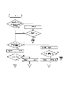
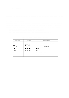
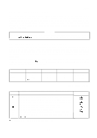
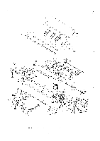
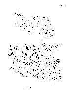
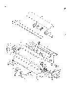
REV.-A 5.3.2 Control Circuit The control circuit can be repaired using the diagnostic tool to identify the problem. Table 5-7 lists the main parts of the control circuit. Table 5-7. Control Circuit Parts List Location 4B 3A 7A 5A, 6A 2A 4A Q1-Q9, Q16 Q15 Q17 Q 18-Q21 Q22, Q25, Q30 Q23, Q24 Name MPD78 10HG E05A15HA E05A16GA HM6264ALSP STK6722H 27256 2SC3987 2SB76SK 2SB1318 2SD560(4) 2SC1815 2SA1015 Description Main CPU 15 MHz Gate Array Gate Array Static RAM 64K bit Hybrid IC, Carriage Controller 32K Byte P-ROM 60V t 10V, 3A, 2W 120V, 3A, 1.5W 100V, 3A, 1.2W 120V, 5A, 1.5W 60V, 150mA, 400mW 50V, 150mA, 400mW 5.4.3 Model-3 B10/3B60 Printer Mechanism Use the diagnostic tooI to detect malfunctions among the carriage motor, paper-feed motor, and sensor, Table 5-8 lists the specifications for these components, use the printing test, and also inspect visually. Table 5-8. Electric Device List Name Carriage Motor Paper Feed Motor Plunger Type Voltage : Coil Resistance : Excitation : Type Voltage : Coil Resistance : Excitation : Type Voltage : Coil Resistance : Description 4-phase, 200 pole stepper motor Driving +36VDC, Holding . . . +5VDC 11 Q & 7% (25 "C/phase) 1-2 phase, 2-2 phase 4-phase, 48 pole stepper motor Driving +36VDC, Holding . . . +5VDC 78 Q A7Q (25 "C/phase) 2-2 phase Solenoid Driving . . . +36VDC, Holding . . . +5VDC No operation . . . OV 2 2 f-l *5% (20"C) 5-20
-
 1
1 -
2
-
3
-
4
-
5
-
6
-
7
-
8
-
9
-
10
-
11
-
12
-
13
-
14
-
15
-
16
-
17
-
18
-
19
-
20
-
21
-
22
-
23
-
24
-
25
-
26
-
27
-
28
-
29
-
30
-
31
-
32
-
33
-
34
-
35
-
36
-
37
-
38
-
39
-
40
-
41
-
42
-
43
-
44
-
45
-
46
-
47
-
48
-
49
-
50
-
51
-
52
-
53
-
54
-
55
-
56
-
57
-
58
-
59
-
60
-
61
-
62
-
63
-
64
-
65
-
66
-
67
-
68
-
69
-
70
-
71
-
72
-
73
-
74
-
75
-
76
-
77
-
78
-
79
-
80
-
81
-
82
-
83
-
84
-
85
-
86
-
87
-
88
-
89
-
90
-
91
-
92
-
93
-
94
-
95
-
96
-
97
-
98
-
99
-
100
-
101
-
102
-
103
-
104
-
105
-
106
-
107
-
108
-
109
-
110
-
111
-
112
-
113
-
114
-
115
-
116
-
117
-
118
-
119
-
120
-
121
-
122
-
123
-
124
-
125
-
126
-
127
-
128
-
129
-
130
-
131
-
132
-
133
-
134
-
135
-
136
-
137
-
138
-
139
-
140
-
141
-
142
-
143
-
144
-
145
-
146
-
147
-
148
-
149
-
150
-
151
-
152
-
153
-
154
-
155
-
156
-
157
-
158
-
159
-
160
-
161
-
162
-
163
-
164
-
165
-
166
-
167
-
168
-
169
-
170
-
171
-
 172
172 -
 173
173 -
 174
174 -
 175
175 -
 176
176 -
 177
177 -
 178
178 -
 179
179 -
 180
180 -
 181
181 -
 182
182 -
183
-
184
-
185
-
186
-
187
-
188
-
189
-
190
-
191
-
192
-
193
-
194
-
195
-
196
-
197
-
198
-
199
-
200
-
201
-
202
-
203
-
204
-
205
-
206
-
207
-
208
-
209
-
210
-
211
-
212
-
213
-
214
-
215
-
216
-
217
-
218
-
219
-
220
-
221
-
222
-
223
-
224
-
225
 |
 |
