Epson LQ 1050 Technical Manual - Page 92
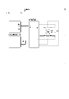
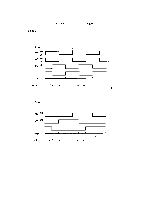
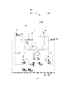
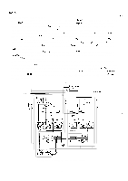
Carriage Motor Control Circuit
 |
View all Epson LQ 1050 manuals
Add to My Manuals
Save this manual to your list of manuals |
Page 92 highlights
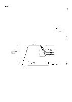
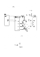
REV.-A Detailed Operation (Figure 2-39.) g,:, * q When the + 5V supply voltage is applied to the STK6722HZ (IC2A), the triangular waveform circuit "'" in the H-IC starts oscillation and outputs the reference signal (approx. 24KHz) for chopper control. q Because the output of comparator IC2 (point Q) is high (input at the plus side > input at the minus side) when the printer power is turned on, TR7 turns on and base current flows to TR 1. When a high signal (AO 1: low) is input to the base of TR3, TR3 turns on, and coil current ICA flows from VCCI to TR 1 to phase A to D5 to TR3 to R 13. ICA gradually increases due to the reactance of the motor coil. Voltage VR13 across limiter resistance R13 increases. When VR13 becomes the same as the VREF at pin 8 (from the reference voltage generation circuit), the output of IC2 (point Q) goes low, TR7 turns off, and TR 1 turns off. Then ICA starts decreasing. When VR13 becomes less than VREF, the output of IC2 goes high again. q The surge voltage (also called flyback voltage) generated when TR3 is cut off by the zener diode ZD 1 (approx. 47V) between the collector and base of transistor Q5, and is absorbed by transistor Q5 to protect TR3 from being damaged. q When the carriage motor stops, the motor drive pulses are fixed at a set value to hold the carriage motor. At this time, H-IC is powered down to prevent it from overheating. When the power down ; operation is performed (when the carriage motor is held), PD 1 of the E05A 16GA (IC7A) goes low, '"--- and TR 11 turns on to drop the reference voltage at the plus side of IC2. As a result, the load on VCOMAB is reduced and H-IC is effectively powered down, At this time, approximately 5V is supplied to VCOMAB by PWM control. cot -8 '"'I 'w+ I I 1 1W " ld'A T1 I II 1 Ott I 1 I I .W . -,,. K '7:F T 1 II t II - I 1 1 I I ,I I I 1 1T Figure 2-39. Carriage Motor Control Circuit 2-48
-
 1
1 -
2
-
3
-
4
-
5
-
6
-
7
-
8
-
9
-
10
-
11
-
12
-
13
-
14
-
15
-
16
-
17
-
18
-
19
-
20
-
21
-
22
-
23
-
24
-
25
-
26
-
27
-
28
-
29
-
30
-
31
-
32
-
33
-
34
-
35
-
36
-
37
-
38
-
39
-
40
-
41
-
42
-
43
-
44
-
45
-
46
-
47
-
48
-
49
-
50
-
51
-
52
-
53
-
54
-
55
-
56
-
57
-
58
-
59
-
60
-
61
-
62
-
63
-
64
-
65
-
66
-
67
-
68
-
69
-
70
-
71
-
72
-
73
-
74
-
75
-
76
-
77
-
78
-
79
-
80
-
81
-
82
-
83
-
84
-
85
-
86
-
 87
87 -
 88
88 -
 89
89 -
 90
90 -
 91
91 -
 92
92 -
 93
93 -
 94
94 -
 95
95 -
 96
96 -
 97
97 -
98
-
99
-
100
-
101
-
102
-
103
-
104
-
105
-
106
-
107
-
108
-
109
-
110
-
111
-
112
-
113
-
114
-
115
-
116
-
117
-
118
-
119
-
120
-
121
-
122
-
123
-
124
-
125
-
126
-
127
-
128
-
129
-
130
-
131
-
132
-
133
-
134
-
135
-
136
-
137
-
138
-
139
-
140
-
141
-
142
-
143
-
144
-
145
-
146
-
147
-
148
-
149
-
150
-
151
-
152
-
153
-
154
-
155
-
156
-
157
-
158
-
159
-
160
-
161
-
162
-
163
-
164
-
165
-
166
-
167
-
168
-
169
-
170
-
171
-
172
-
173
-
174
-
175
-
176
-
177
-
178
-
179
-
180
-
181
-
182
-
183
-
184
-
185
-
186
-
187
-
188
-
189
-
190
-
191
-
192
-
193
-
194
-
195
-
196
-
197
-
198
-
199
-
200
-
201
-
202
-
203
-
204
-
205
-
206
-
207
-
208
-
209
-
210
-
211
-
212
-
213
-
214
-
215
-
216
-
217
-
218
-
219
-
220
-
221
-
222
-
223
-
224
-
225
 |
 |
