Epson LQ 1050 Technical Manual - Page 134
Friction/Tractor Sensor Removal
 |
View all Epson LQ 1050 manuals
Add to My Manuals
Save this manual to your list of manuals |
Page 134 highlights
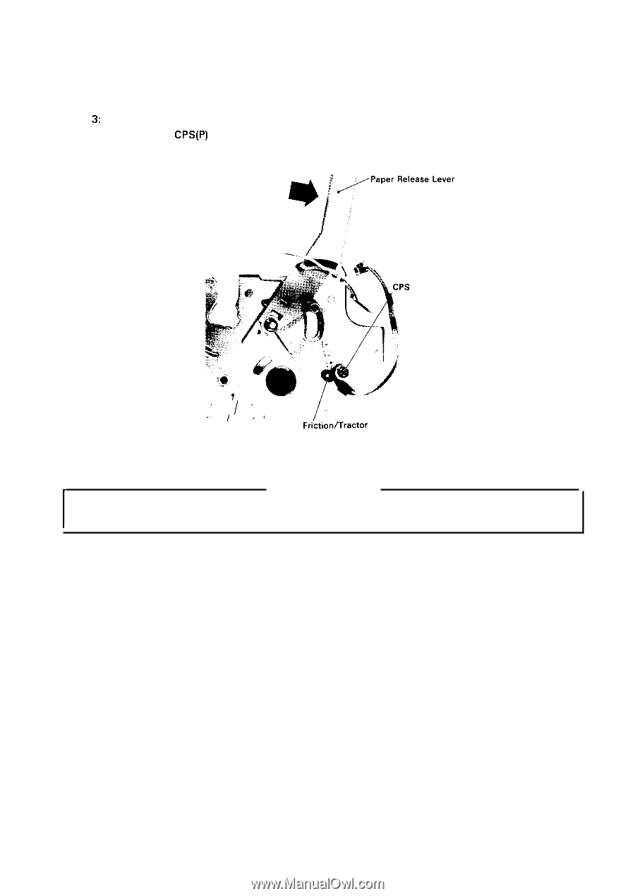
REV.-A 4.2.5.8 Friction/Tractor Sensor Removal Step 1: Remove the printer mechanism (Refer to Section 4.2.5. 1.). Step 2: Position the paper release lever at its back setting. Step 3: Remove the paper feed motor (Refer to Section 4.2.5.7). Step 4: Remove the CPS(P) (3 X 10) screw securing the friction/tractor sensor to the side frame R, then remove the sensor. (P) (3 x 10) .. .'"" I I ' a' Side Frame R / I Frictionfiractor Sensor Figure 4-27. Friction/Tractor Sensor Removal ASSEMBLY POINT Make sure of the sensor direction and set in place before mounting the friction/tractor sensor on the side frame R. 4-21
-
 1
1 -
2
-
3
-
4
-
5
-
6
-
7
-
8
-
9
-
10
-
11
-
12
-
13
-
14
-
15
-
16
-
17
-
18
-
19
-
20
-
21
-
22
-
23
-
24
-
25
-
26
-
27
-
28
-
29
-
30
-
31
-
32
-
33
-
34
-
35
-
36
-
37
-
38
-
39
-
40
-
41
-
42
-
43
-
44
-
45
-
46
-
47
-
48
-
49
-
50
-
51
-
52
-
53
-
54
-
55
-
56
-
57
-
58
-
59
-
60
-
61
-
62
-
63
-
64
-
65
-
66
-
67
-
68
-
69
-
70
-
71
-
72
-
73
-
74
-
75
-
76
-
77
-
78
-
79
-
80
-
81
-
82
-
83
-
84
-
85
-
86
-
87
-
88
-
89
-
90
-
91
-
92
-
93
-
94
-
95
-
96
-
97
-
98
-
99
-
100
-
101
-
102
-
103
-
104
-
105
-
106
-
107
-
108
-
109
-
110
-
111
-
112
-
113
-
114
-
115
-
116
-
117
-
118
-
119
-
120
-
121
-
122
-
123
-
124
-
125
-
126
-
127
-
128
-
 129
129 -
 130
130 -
 131
131 -
 132
132 -
 133
133 -
 134
134 -
 135
135 -
 136
136 -
 137
137 -
 138
138 -
 139
139 -
140
-
141
-
142
-
143
-
144
-
145
-
146
-
147
-
148
-
149
-
150
-
151
-
152
-
153
-
154
-
155
-
156
-
157
-
158
-
159
-
160
-
161
-
162
-
163
-
164
-
165
-
166
-
167
-
168
-
169
-
170
-
171
-
172
-
173
-
174
-
175
-
176
-
177
-
178
-
179
-
180
-
181
-
182
-
183
-
184
-
185
-
186
-
187
-
188
-
189
-
190
-
191
-
192
-
193
-
194
-
195
-
196
-
197
-
198
-
199
-
200
-
201
-
202
-
203
-
204
-
205
-
206
-
207
-
208
-
209
-
210
-
211
-
212
-
213
-
214
-
215
-
216
-
217
-
218
-
219
-
220
-
221
-
222
-
223
-
224
-
225
 |
 |
REV.-A
4.2.5.8
Step 1:
Step 2:
Step
3:
Step 4:
Friction/Tractor Sensor Removal
Remove the printer mechanism (Refer to Section 4.2.5. 1.).
Position the paper release lever at its back setting.
Remove the paper feed motor (Refer to Section 4.2.5.7).
Remove the
CPS(P)
(3 X 10) screw securing the friction/tractor sensor to the side frame R,
then remove the sensor.
(P) (3 x
10)
‘“”
I
‘
/
.
.
.
I
a’
I
Side Frame R
Frictionfiractor
Sensor
Figure 4-27. Friction/Tractor Sensor Removal
ASSEMBLY POINT
Make sure of the sensor direction and set in place before mounting the friction/tractor sensor on
the side frame R.
4-21