Epson LQ 1050 Technical Manual - Page 25
Rev.-a, L/dc3, Slct-in, Dcl/dc3, L/dc3
 |
View all Epson LQ 1050 manuals
Add to My Manuals
Save this manual to your list of manuals |
Page 25 highlights
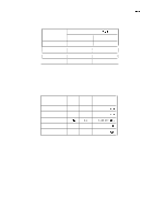
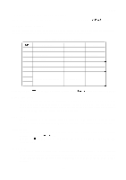
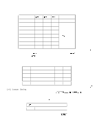
REV.-A Table 1-18 shows the printer select/deselect (DC l/DC3) control, including relations among ON-LINE, :):> f. . SLCT-IN input, DC 1 /DC3, and interface signals. Table 1-18. Printer Select/Deselect Control ON-LINE SW OFF-LINE ON-LINE SLCT-IN HIGH/LOW HIGH Dcl/Dc3 DC l/DC3 DC 1 DC3 LOW DC 1 DC3 ERROR BUSY ACKNLG DATA ENTRY LOW HIGH No pulse Disable HIGH LOW\HIGH (During data entry) Pulse output after entry Enable (Normal Process) HIGH LOW\HIGH (During data entry) Pulse output after entry Enable (Waits DC1. See Note 2) HIGH LOW/HIGH Pulse output (During data after entry HIGH entry) LOW/HIGH Pulse output Enable (Normal Process) L (During data after entry entry) NOTES: 1. In the Table 1-18, it is assumed that no ERROR status exists other than that attributable to OFF-LINE mode. 2. Once the printer is deselected by the DC3 code, the printer will not revert the selected state unless the DC 1 code is input again. (In the deselected state, the printer ignores input data until the DC 1 code is received.) 3. The DC 1 and DC3 codes are enabled only when the SLCT-IN signal (Input Connector No.36 for the parallel interface unit) is HIGH and printer power is initialized. 4. If the SLCT-IN signal is LOW when the printer is initialized, DC l/DC3 printer select/deselect control is invalidated, and these control codes are ignored. 5. If the SLCT-IN signal is HIGH and is not set to LOW by jumper 6 when printer initialized, the printer starts from the selected (DC 1 ) state. f-: 1-16
-
 1
1 -
2
-
3
-
4
-
5
-
6
-
7
-
8
-
9
-
10
-
11
-
12
-
13
-
14
-
15
-
16
-
17
-
18
-
19
-
 20
20 -
 21
21 -
 22
22 -
 23
23 -
 24
24 -
 25
25 -
 26
26 -
 27
27 -
 28
28 -
 29
29 -
 30
30 -
31
-
32
-
33
-
34
-
35
-
36
-
37
-
38
-
39
-
40
-
41
-
42
-
43
-
44
-
45
-
46
-
47
-
48
-
49
-
50
-
51
-
52
-
53
-
54
-
55
-
56
-
57
-
58
-
59
-
60
-
61
-
62
-
63
-
64
-
65
-
66
-
67
-
68
-
69
-
70
-
71
-
72
-
73
-
74
-
75
-
76
-
77
-
78
-
79
-
80
-
81
-
82
-
83
-
84
-
85
-
86
-
87
-
88
-
89
-
90
-
91
-
92
-
93
-
94
-
95
-
96
-
97
-
98
-
99
-
100
-
101
-
102
-
103
-
104
-
105
-
106
-
107
-
108
-
109
-
110
-
111
-
112
-
113
-
114
-
115
-
116
-
117
-
118
-
119
-
120
-
121
-
122
-
123
-
124
-
125
-
126
-
127
-
128
-
129
-
130
-
131
-
132
-
133
-
134
-
135
-
136
-
137
-
138
-
139
-
140
-
141
-
142
-
143
-
144
-
145
-
146
-
147
-
148
-
149
-
150
-
151
-
152
-
153
-
154
-
155
-
156
-
157
-
158
-
159
-
160
-
161
-
162
-
163
-
164
-
165
-
166
-
167
-
168
-
169
-
170
-
171
-
172
-
173
-
174
-
175
-
176
-
177
-
178
-
179
-
180
-
181
-
182
-
183
-
184
-
185
-
186
-
187
-
188
-
189
-
190
-
191
-
192
-
193
-
194
-
195
-
196
-
197
-
198
-
199
-
200
-
201
-
202
-
203
-
204
-
205
-
206
-
207
-
208
-
209
-
210
-
211
-
212
-
213
-
214
-
215
-
216
-
217
-
218
-
219
-
220
-
221
-
222
-
223
-
224
-
225
 |
 |
