HP BL260c HP BladeSystem c-Class Enclosure Troubleshooting Guide - Page 32
Procedures: Power supply failure, Symptom, Initial step, Required steps
 |
UPC - 883585668663
View all HP BL260c manuals
Add to My Manuals
Save this manual to your list of manuals |
Page 32 highlights
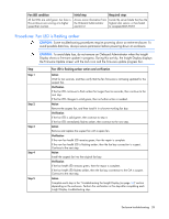
Symptom Initial step Required steps The power LED is on. The fault LED is off. The Insight Display reports power supply failure. Use the power supply bay Begin with step 4. status on the Insight Display Health Summary to verify the success or failure of each step. Procedures: Power supply failure CAUTION: Some troubleshooting procedures require powering down an entire enclosure. To avoid possible data loss, always secure permission before powering down an enclosure. CAUTION: To avoid data loss, do not remove an Onboard Administrator when the Insight Display shows a firmware update in progress. During this activity, the Insight Display displays the Firmware Update screen with the Lock icon and the firmware update progress bar. Step Step 1 Step 2 Caution Step 3 Power supply failure action and verification Action Verify that the AC power cord is connected properly to the AC source and to the power supply reporting the error. Verification If the power supply LEDs indicate normal condition, then the repair is complete. If the power supply LEDs indicate other than normal condition, then continue to the next step. Action Remove the suspect power supply, and then replace it with a service spare power supply. Verification If the power supply LEDs indicate normal condition, then the original power supply had failed and the repair is complete. • If the power supply LEDs indicate other than normal condition and you are troubleshooting an HP BladeSystem c7000 Enclosure, then continue to the next step. • If the power supply LEDs indicate other than normal condition and you are troubleshooting an HP BladeSystem c3000 Enclosure, then continue to step 4. Request authorization to power down the enclosure. Do not continue to the next step until you receive proper authorization. Action Test the AC power input module: 1 Remove the AC power input module. 2 Install a known-working AC power input module or service spare part. 3 Reconnect all power cords. Verification If the power supply LEDs indicate normal condition, then the AC input module had failed and the repair is complete. If the power supply LEDs still indicate other than normal condition, then continue to step 14. Enclosure troubleshooting 32
-
 1
1 -
2
-
3
-
4
-
5
-
6
-
7
-
8
-
9
-
10
-
11
-
12
-
13
-
14
-
15
-
16
-
17
-
18
-
19
-
20
-
21
-
22
-
23
-
24
-
25
-
26
-
 27
27 -
 28
28 -
 29
29 -
 30
30 -
 31
31 -
 32
32 -
 33
33 -
 34
34 -
 35
35 -
 36
36 -
 37
37 -
38
-
39
-
40
-
41
-
42
-
43
-
44
-
45
-
46
-
47
-
48
-
49
-
50
-
51
-
52
-
53
-
54
-
55
-
56
-
57
-
58
-
59
-
60
-
61
-
62
-
63
-
64
-
65
-
66
-
67
-
68
-
69
-
70
-
71
-
72
-
73
-
74
-
75
-
76
-
77
-
78
-
79
-
80
-
81
-
82
-
83
-
84
-
85
-
86
-
87
-
88
-
89
-
90
-
91
-
92
-
93
-
94
-
95
-
96
-
97
-
98
-
99
-
100
-
101
-
102
-
103
-
104
-
105
-
106
 |
 |
