HP BL260c HP BladeSystem c-Class Enclosure Troubleshooting Guide - Page 33
Power supply failure action and verification, Step 4, Action, Verification
 |
UPC - 883585668663
View all HP BL260c manuals
Add to My Manuals
Save this manual to your list of manuals |
Page 33 highlights
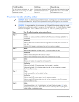
Step Step 4 Step 5 Step 6 Step 7 Power supply failure action and verification Action To troubleshoot the component connectors, perform the following: 1 Note the location of each device to be sure that each device is later installed in the original bay. 2 Remove all devices and modules installed in the enclosure. 3 Attempt to keep cables attached to all rear modules. If this is not possible, then note cable locations to be sure the cables are connected to the module correctly when the module is reinstalled. 4 Examine all the connectors for damage. Verification Replace all devices that have damaged connectors, and replace all devices with connectors mating to damaged connectors. For all other devices connected directly to the midplane, always replace the damaged device and the midplane assembly. Continue to the next step. If no visible damage exists, then continue to the next step. Action Reinstall and troubleshoot the power supplies to locate shorted power supplies: 1 Install all power supplies one at a time into their original bays. 2 Be sure that the power cord is connected and that the power is on. 3 Verify the power LED and fault LED for each power supply. Verification If the power supply power LED is on and the fault LED is off, then the power supply is operating normally. The repair is complete. If the power supply fault LED is on or the Power LED is off, continue to the next step. Action Remove the suspect power supply, and then install a service spare power supply. Verification If the power supply power LED is on and the fault LED is off, then the suspect power supply has failed. Continue to the next step. If the fault LED is on, then the original power supply did not fail. Remove the service spare power supply and install the original power supply. Continue to step 14. Action Install the OA tray. Enclosure troubleshooting 33
-
 1
1 -
2
-
3
-
4
-
5
-
6
-
7
-
8
-
9
-
10
-
11
-
12
-
13
-
14
-
15
-
16
-
17
-
18
-
19
-
20
-
21
-
22
-
23
-
24
-
25
-
26
-
27
-
 28
28 -
 29
29 -
 30
30 -
 31
31 -
 32
32 -
 33
33 -
 34
34 -
 35
35 -
 36
36 -
 37
37 -
 38
38 -
39
-
40
-
41
-
42
-
43
-
44
-
45
-
46
-
47
-
48
-
49
-
50
-
51
-
52
-
53
-
54
-
55
-
56
-
57
-
58
-
59
-
60
-
61
-
62
-
63
-
64
-
65
-
66
-
67
-
68
-
69
-
70
-
71
-
72
-
73
-
74
-
75
-
76
-
77
-
78
-
79
-
80
-
81
-
82
-
83
-
84
-
85
-
86
-
87
-
88
-
89
-
90
-
91
-
92
-
93
-
94
-
95
-
96
-
97
-
98
-
99
-
100
-
101
-
102
-
103
-
104
-
105
-
106
 |
 |
